Control for an earth moving system while performing turns

a technology of earth moving system and control system, which is applied in the direction of process and machine control, instruments, navigation instruments, etc., can solve the problems of affecting the operation of the machine, inclinometer providing an erroneous output, and subject to error, so as to reduce the unneeded vertical movement of the blade that might otherwise result from an erroneous inclinometer reading

Active Publication Date: 2011-06-28
CATERPILLAR TRIMBLE CONTROL TECH
View PDF44 Cites 18 Cited by
  • Summary
  • Abstract
  • Description
  • Claims
  • Application Information

AI Technical Summary

Benefits of technology

[0008]These needs are met by an earthmoving method and system according to the present invention, which includes a laser transmitter for transmitting a reference beam of laser light, and a bulldozer, having a frame and a cutting blade supported by a blade support extending from the frame. The blade support includes hydraulic cylinders for raising and lowering the blade in relation to the frame. A laser receiver is mounted on a mast extending upward from, and movable with, the cutting blade. The laser receiver senses the reference beam of laser light. An inclinometer is mounted for movement with the cutting blade to provide an indication of the inclination of the blade. A sensor detects turning of the bulldozer. A control is responsive to the laser receiver, to the inclinometer, and to the sensor, for controlling the operation of the cylinders and adjusting the position of the blade. The control keeps the blade at an unchanged level when rapid turning of the bulldozer is detected. As a consequence, undesired vertical movement of the blade that might otherwise result from an erroneous inclinometer reading is reduced.
[0009]The laser transmitter may comprise a transmitter that provides a rotating beam of laser light. The control then determines the position of the cutting blade each time the receiver is illuminated by the rotating beam. The sensor may comprise a sensor connected to the steering system of the bulldozer to detect turning. The sensor may comprise a circuit for detecting a rapid change in the output of the inclinometer. The sensor may comprise a circuit for detecting a rapid change in the output of the inclinometer without an operation of the hydraulic cylinders that would account for such a change. The control may keep the blade at an unchanged level for a preset period of time after turning of the bulldozer is discontinued, whereby erroneous vertical movement of the blade is reduced.
[0011]The sensor may be connected to the steering system of the bulldozer. The sensor may detect a rapid change in the output of the inclinometer, and especially a rapid change in the output of the inclinometer without an operation of the hydraulic cylinders that would account for such a change. The control may maintain the blade at an unchanged level for a preset period of time after turning the bulldozer is discontinued. By this arrangement, erroneous vertical movement of the blade may be reduced.

Problems solved by technology

Inclinometers of this type are gravity based and, although typically damped to reduce noise from high frequency vibration, are subject to error due to acceleration experience during operation of the machine.
More specifically, when a machine such as a bulldozer makes a turn as it is moving at a relatively rapid speed, the inclinometer will provide an erroneous output, indicating that the blade is inclined at an angle that differs significantly from the actual orientation of the blade.
This erroneous output will have a deleterious effect upon the operation of the machine.
If the machine is the type in which a height sensor is carried on a mast attached to the blade, the system will compute an erroneous blade height.
This will be displayed, and, if the system is operating in an automatic mode, may cause the blade to be lowered erroneously.
If the inclinometer output is being used to display or control blade inclination, an error in the display or the control as to blade orientation will also occur.

Method used


Image

  • Control for an earth moving system while performing turns
  • Control for an earth moving system while performing turns
  • Control for an earth moving system while performing turns

Examples


Embodiment Construction

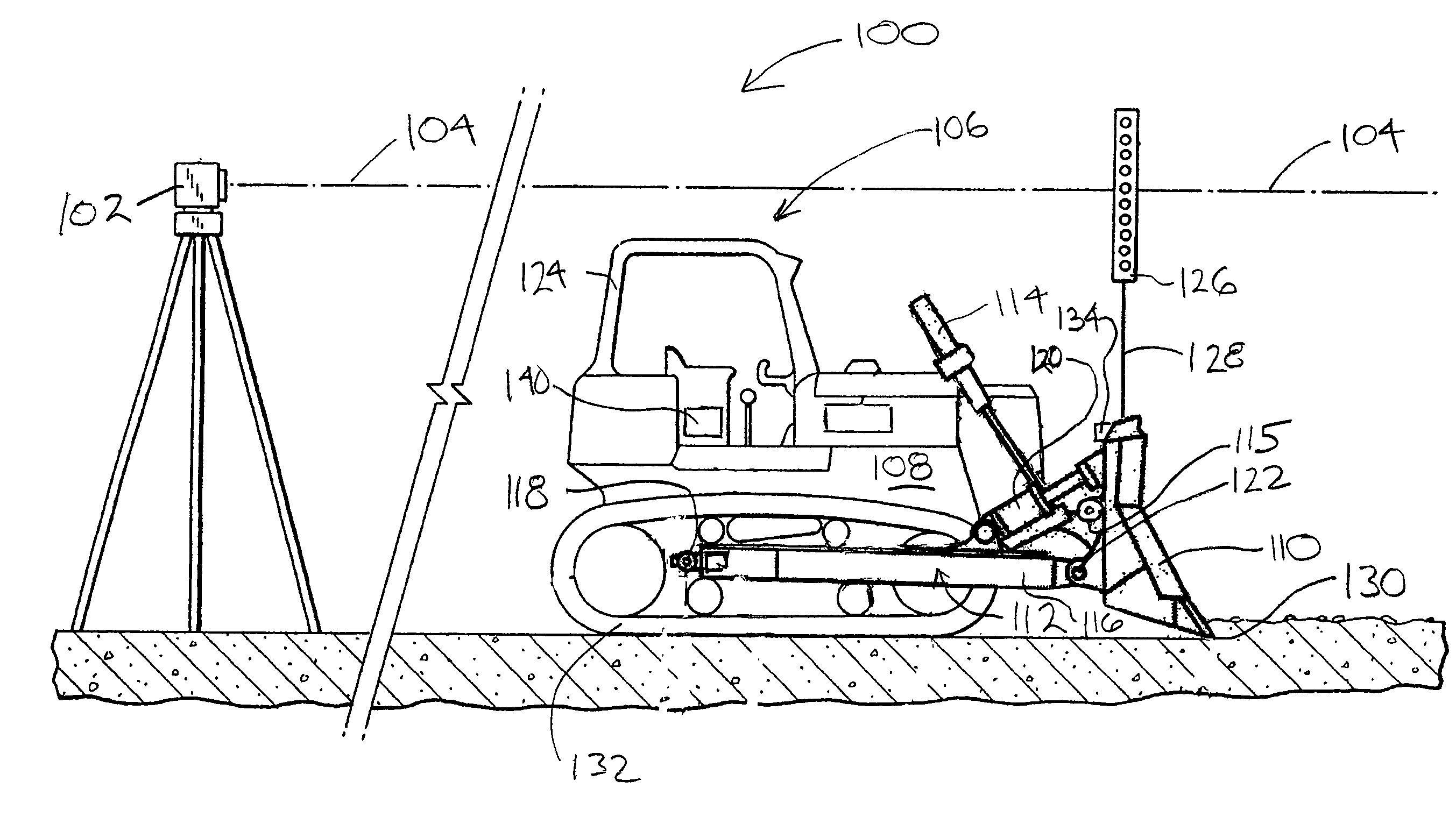
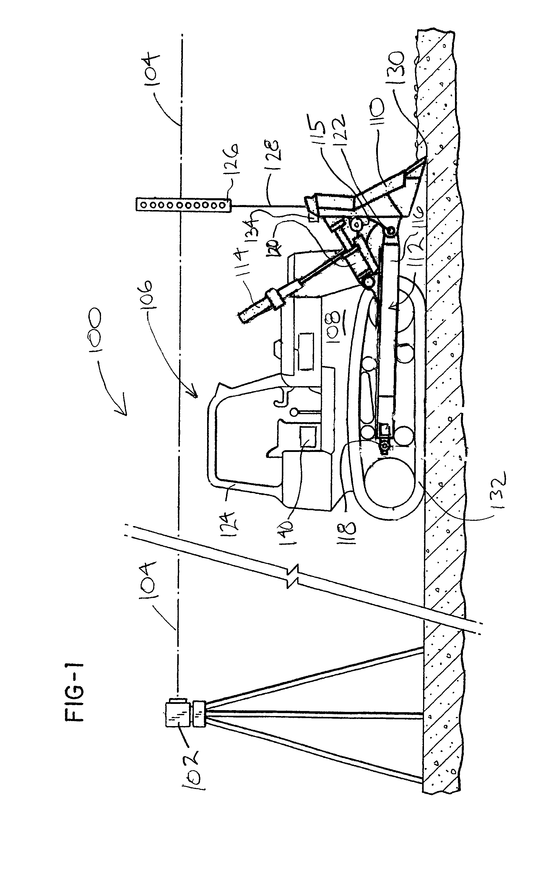
[0016]Reference is now made to FIG. 1, which illustrates an earthmoving system 100, constructed according to the present invention. The system 100 includes a laser transmitter 102 for transmitting a reference beam of laser light 104. The beam of laser light is rotated about a vertical axis to define a horizontal reference plane. As is known, the reference plane may be tilted at a precisely controlled angle to the horizontal if a grade is to be defined by the plane of light.

[0017]The system 100 further includes a bulldozer 106, having a frame 108 and a cutting blade 110. The cutting blade 110 is supported by a blade support 112 that extends from the frame 108. The blade support 112 includes a pair of hydraulic cylinders 114, only one of which is shown in FIG. 1, for raising and lowering the blade 110 in relation to the frame. A pair of arms 116, one of which is shown in FIG. 1, are attached to opposite ends of blade support 112 and pivotally attached to the frame 108 at 118. Cylinder...


PUM


Abstract

An earthmoving system, includes in one embodiment a laser transmitter for transmitting a reference beam of laser light, and a laser receiver mounted on a mast on the bulldozer blade. The bulldozer has a frame and a cutting blade supported by a blade support extending from said frame. The blade support includes hydraulic cylinders for raising and lowering the blade in relation to said frame, and for tilting the blade along its length. The mast extends upward from, and is movable with, the blade. An inclinometer is mounted for movement with the blade to provide an indication of the inclination of the blade. A sensor detects turning of the bulldozer. A control is responsive to the laser receiver, to the inclinometer, and to the sensor, for controlling the operation of said cylinders and adjusting the position of said blade. When rapid turning of said bulldozer is detected the control operates to reduce the errors that would otherwise result from an erroneous inclinometer output.

Description

CROSS-REFERENCE TO RELATED APPLICATIONS[0001]Not applicable.STATEMENT REGARDING FEDERALLY SPONSORED RESEARCH OR DEVELOPMENT[0002]Not applicable.BACKGROUND OF THE INVENTION[0003]Various control arrangements have been developed to control earthmoving devices, such as bulldozers, so that a tract of land can be graded to a desired level or contour. A number of systems have been developed in which the position of the earthmoving apparatus is determined with a laser, GPS or optically referenced positioning system. In such systems, a tract of land is surveyed and a site plan is designed with the desired finish contour. From the tract survey and the site plan, a cut-fill map is produced showing amounts of cut or fill needed in specific areas of the tract of land to produce the desired finish contour. The information is then stored in the computer control system on the earthmoving apparatus.[0004]In one type of control system for earthmoving apparatus, a position reference receiver, such as ...

Claims


Application Information

Patent Timeline
Patent Type & Authority Patents(United States)
IPC IPC(8): G06F19/00
CPCE02F3/847G05D1/0891E02F9/2037
Inventor GREEN, FRANCISCO
Owner CATERPILLAR TRIMBLE CONTROL TECH
Why Eureka
Try Eureka