
Integrated continuous batch tunnel washer

a technology of continuous batch and tunnel washer, which is applied in the direction of other washing machines, detergent compositions, textiles and paper, etc., can solve the problems of wasting energy, reducing the effectiveness of washing chemicals, and dilution of washing chemicals, so as to improve the rinsing capacity, reduce the number of components, and reduce water consumption

Active Publication Date: 2011-07-05
PELLERIN MILNOR
View PDF14 Cites 29 Cited by
  • Summary
  • Abstract
  • Description
  • Claims
  • Application Information

AI Technical Summary

Benefits of technology

"The present invention improves the current art of laundering fabric articles or textiles by reducing water consumption, improving rinsing capability, saving valuable floor space in the laundry, and reducing the number of components required to perform the function of laundering. The invention achieves this by reducing and / or combining zones, improving the method of processing the textiles, and stopping the counter flow of wash liquor into the modules. The invention uses fresh water in the extractor that can be supplied through an atomizing nozzle while the goods are being extracted at high speed, reducing or eliminating graying of the goods. The method reduces the amount of fresh water required and preserves the washing effectiveness of current counter flow washers to wash heavy soil classifications. The invention provides a higher effective rinsing provided by the spray rinse in the centrifugal extractor because of the pre-rinse in the tunnel washer."

Problems solved by technology

This practice dilutes the washing chemical and reduces its effectiveness.
Additionally, while the bath liquor is being heated, this thermal energy is partially carried away by the counter flow thus wasting energy while a desired temperature value is achieved.

Method used


Image

  • Integrated continuous batch tunnel washer
  • Integrated continuous batch tunnel washer
  • Integrated continuous batch tunnel washer

Examples


Embodiment Construction

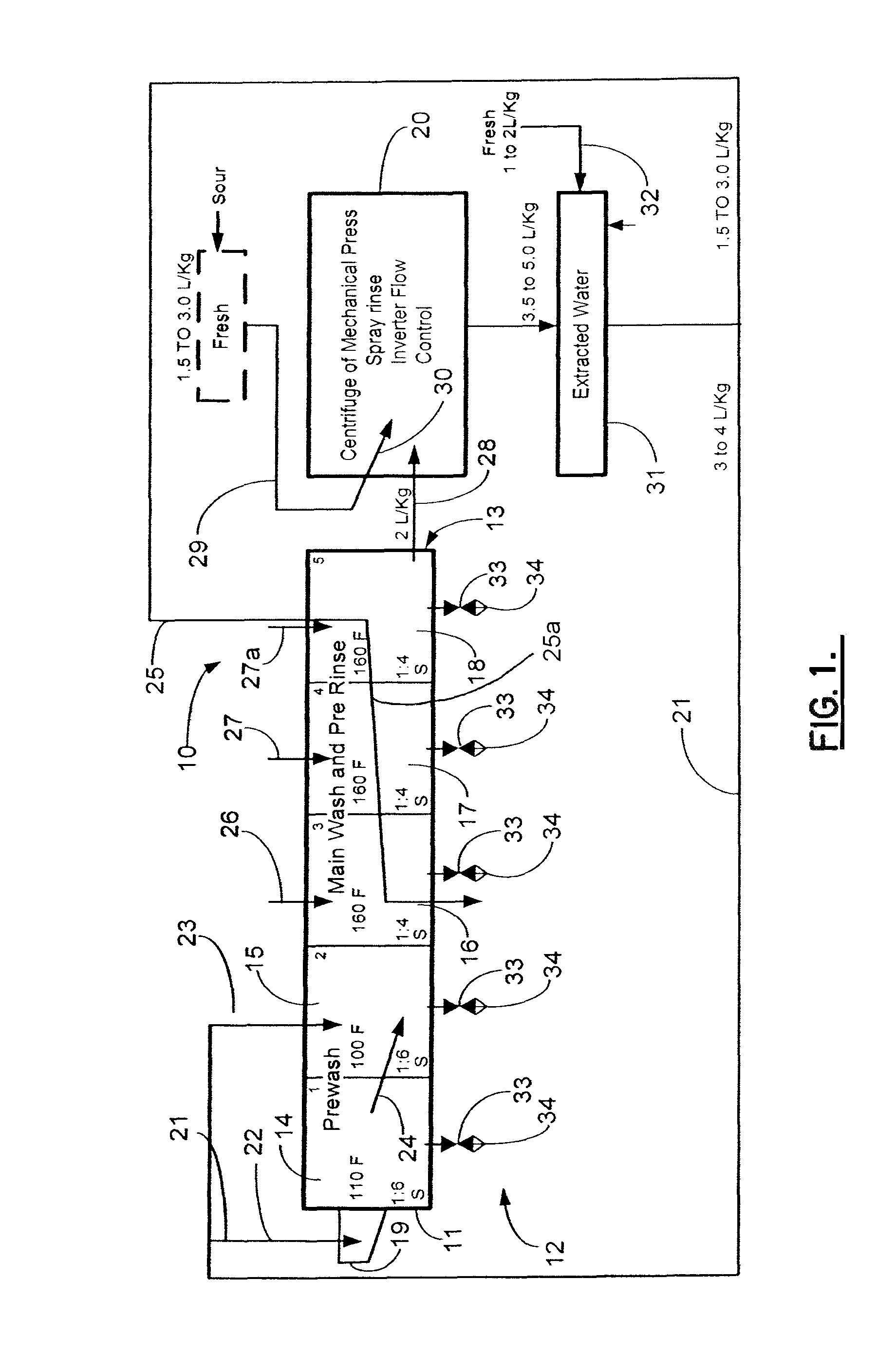
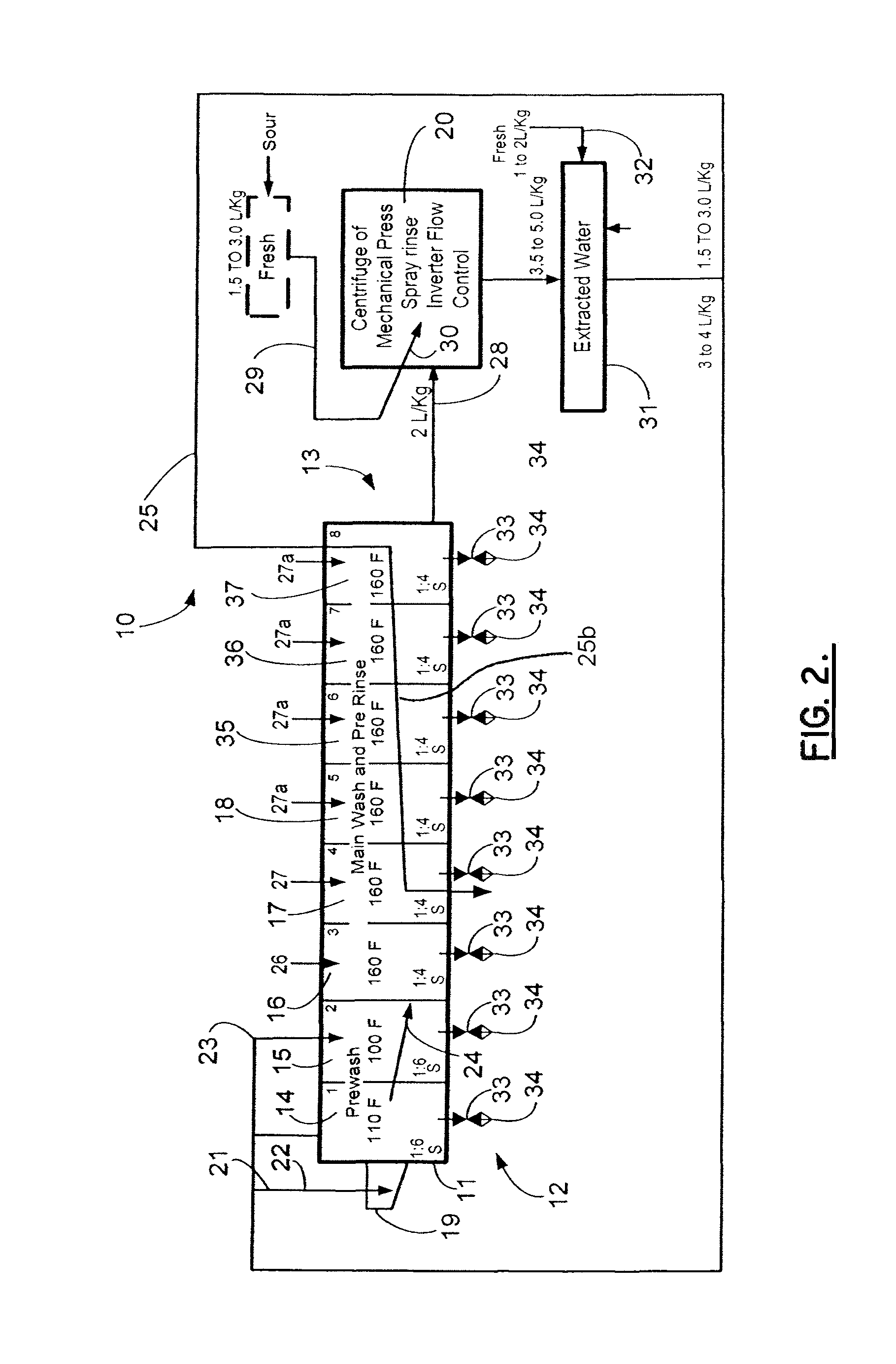
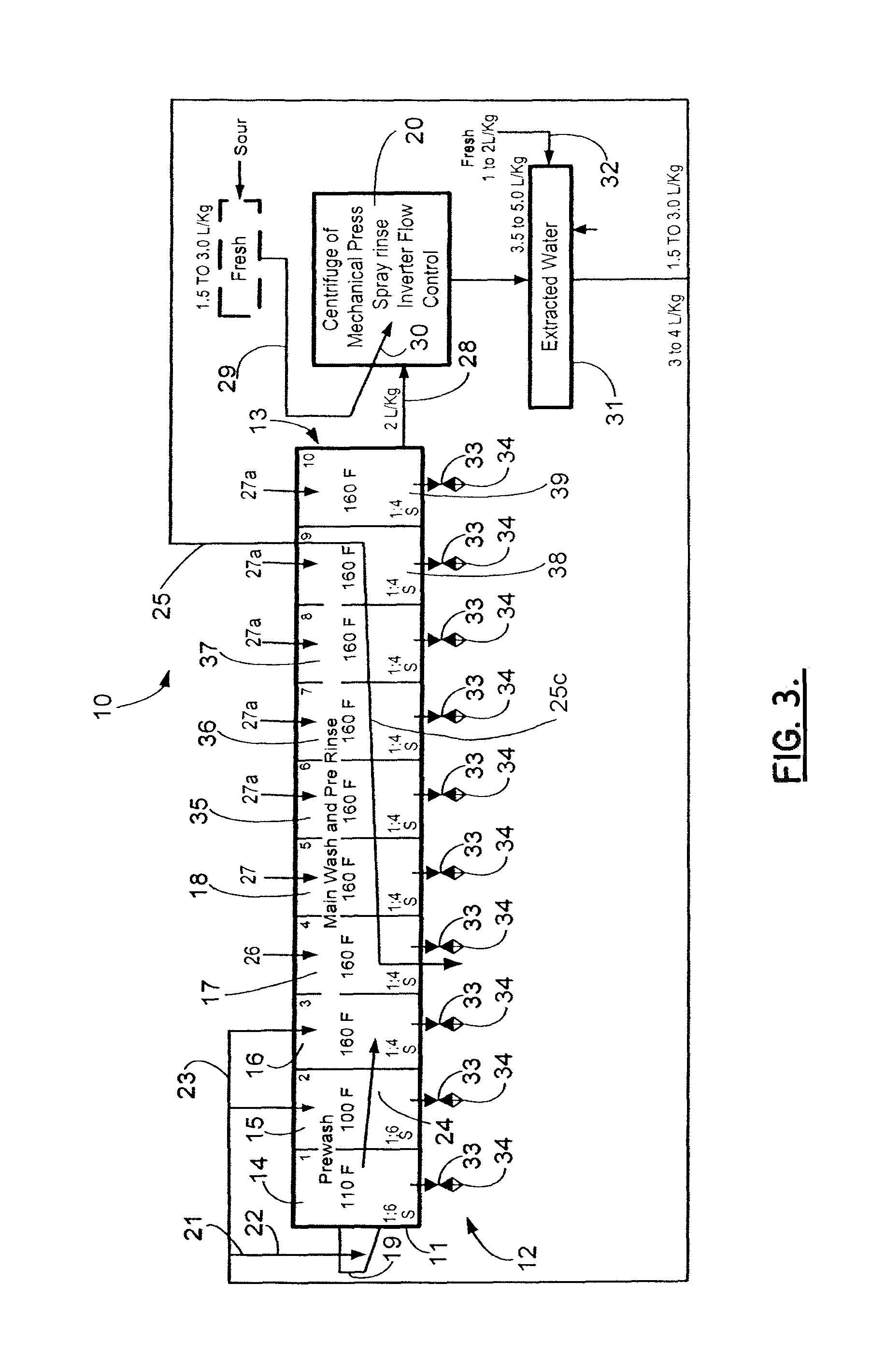
[0030]FIGS. 1-3 show schematic diagrams of the textile washing apparatus of the present invention, designated generally by the numeral 10. Textile washing apparatus 10 provides a tunnel washer 11 having an inlet end portion 12 and an outlet end portion 13. Tunnel washer 11 provides a number of modules such as the modules 14-18 shown in FIG. 1. These modules 14-18 can include a first module 14 and a second module 15 which can be pre-wash modules. The plurality of modules 14-18 can also include modules 16, 17 and 18 which are main wash and pre-rinse modules.

[0031]The total number of modules 14-18 can be more or less than the five (5) shown in FIG. 1. FIG. 2 shows an alternate arrangement that employs a tunnel washer 11 having eight (8) modules 14-18 and 35-37. FIG. 3 shows an alternate arrangement that employs a tunnel washer 11 having ten (10) modules 14-18 and 35-39. In FIG. 2, the modules 14, 15 can be pre-wash modules. In FIG. 3, modules 14, 15, 16 can be pre-wash modules. In FIG....


PUM


Abstract

A method of washing fabric articles in a tunnel washer includes moving the fabric articles from the intake of the washer to the discharge of the washer through first and second sectors that are a pre-wash zone. In the pre-wash zone, liquid is counter flowed in the wash interior along a flow path that is generally opposite the direction of travel of the fabric articles. The fabric articles are transferred to a main wash zone, and a washing chemical is added to the main wash zone. At about the same time, counter flow is reduced or stopped. The main wash zone can be heated as an option. After a period of time (for example, between about 20 and 120 seconds) counter flow is increased. The increased counter flow after chemical treatment amounts to either an intermediate rinse or a pre-rinse depending upon which module or zone the goods occupy. The pre-rinse ensures that the fabric articles are substantially free of soil or the majority of any soil when they are transferred to an extractor for final removal of excess water.

Description

CROSS-REFERENCE TO RELATED APPLICATIONS[0001]Priority of U.S. Provisional Patent Application Ser. No. 61 / 046,120, filed Apr. 18, 2008, incorporated herein by reference, is hereby claimed.STATEMENT REGARDING FEDERALLY SPONSORED RESEARCH OR DEVELOPMENT[0002]Not applicableREFERENCE TO A “MICROFICHE APPENDIX”[0003]Not applicableBACKGROUND OF THE INVENTION[0004]1. Field of the Invention[0005]The present invention relates to continuous batch washers or tunnel washers. More particularly, the present invention relates to an improved method of washing textiles or fabric articles (e.g. clothing, linen, etc.) in a continuous batch tunnel washer wherein the textiles are moved sequentially from one module or zone to the next module or zone including initial pre-wash zones, a plurality of main wash zones, a pre-rinse zone, and then transferred to an extractor that performs the final rinse and that removes water. More particularly, the present invention relates to an improved method of washing tex...

Claims


Application Information

Patent Timeline
Patent Type & Authority Patents(United States)
IPC IPC(8): D06F29/02
CPCD06F31/005
Inventor POY, RUSSELL H.SCHUBERT, KARL
Owner PELLERIN MILNOR
Learn More