Exhaust-gas muffler

a technology of exhaust gas and muffler, which is applied in the direction of heat measurement, cable termination, instruments, etc., can solve the problems of high muffler temperature, microscopically small wear and contact corrosion at the touching locations, and achieve the effect of facilitating the insertion of the plug into the sleeve during assembly, increasing elasticity, and increasing elasticity

Active Publication Date: 2011-07-05
ANDREAS STIHL AG & CO KG
View PDF29 Cites 3 Cited by
  • Summary
  • Abstract
  • Description
  • Claims
  • Application Information

AI Technical Summary

Benefits of technology

[0005]It is an object of the invention to provide an exhaust-gas muffler of the type described above wherein a contamination of the sleeves of the exhaust-gas muffler is avoided in a simple manner.
[0010]Advantageously, the plug has a conical section at the end thereof projecting into the sleeve whereat the plug tapers. In this way, the insertion of the plug into the sleeve during assembly is facilitated. Because of the conical section, the cylindrical section of the plug is shortened so that, overall, an increased elasticity results. It is practical that a plug have a chamfer at its end facing away from the attachment opening. The chamfer too increases the elasticity of the plug at the end of the plug arranged at the outside of the exhaust-gas muffler. Because of the chamfer, projecting edges of the plug, which result when the plug is not pushed completely into the sleeve, can be avoided.
[0011]Advantageously, the plug has a through opening. Because of the through opening, the plug closes the access opening only partially. Here, it is especially provided that the exhaust-gas muffler has an attachment element arranged in the sleeve which extends through the attachment opening and is accessible through the through opening. In this way, the plug need not be disassembled for loosening or fixing the attachment element, for example, for maintenance purposes. The plug can remain in the access opening. The work tool, such as a screw driver or the like, is used to loosen or fix the attachment element. This work tool usually has a significantly lesser outer diameter than the head of the attachment element and the inner diameter of the sleeve. In this way, a through opening in the plug, which is significantly smaller than the head of the attachment element, is sufficient in order to make possible a loosening or fixing of the attachment element after assembly of the attachment element in the sleeve. A contamination of the sleeve is substantially avoided because of the significantly reduced diameter of the through opening.
[0012]Advantageously, the plug has a resilient section which at least partially closes the through opening. The resilient section can be pressed away by the work tool to loosen or fix the attachment element so that the attachment element is accessible. After loosening or fixing the attachment element, the work tool is guided out of the sleeve and the plug so that the resilient section can spring back and the through opening can at least again be partially closed. In this way, and in a simple manner, the access opening is closed during operation and a contamination of the sleeve is avoided and, simultaneously, the attachment element is accessible for a work tool. The resilient section is advantageously arranged at the end of the plug projecting into the sleeve. A simple configuration results when the resilient section is formed by individual wire loops. The resilient section can thereby be formed by a special arrangement of the metal wire in the region of the resilient section. The wire loops are advantageously aligned in the resilient section in one direction and are not connected to each other in the peripheral direction. A resilient expansion is made possible because of the inherent elasticity of the wire.
[0013]It can also be advantageous that the through opening is closed with a closing stopper. To loosen or fix the attachment element, the closing stopper can be removed so that the attachment element is accessible via the through opening. Because of the reduced temperature in the interior of the plug, the closing stopper does not bake together with the plug so that the accessibility of the through opening is ensured. The closing stopper is advantageously arranged at the end of the plug facing away from the attachment opening. Advantageously, the closing stopper has a cylindrical section which projects into the through opening. In this way, and in a simple manner, a fixing of the closing stopper in the plug is achieved. The closing stopper has an edge whose outer diameter is greater than the inner diameter of the through opening. In this way, it can be ensured that the closing stopper cannot be pushed completely into the plug which would make a disassembly of the closing stopper more difficult. The edge of the closing stopper projects beyond the plug so that the closing stopper can be pulled at the edge from the plug.

Problems solved by technology

During operation, vibrations and the high temperatures of the muffler lead, in this region, to the smallest relative movements between the metal loops and the inner wall of the sleeve at each touching location.
These relative movements cause microscopically small wear and contact corrosion at the touching locations.

Method used


Image

  • Exhaust-gas muffler
  • Exhaust-gas muffler
  • Exhaust-gas muffler

Examples


Embodiment Construction

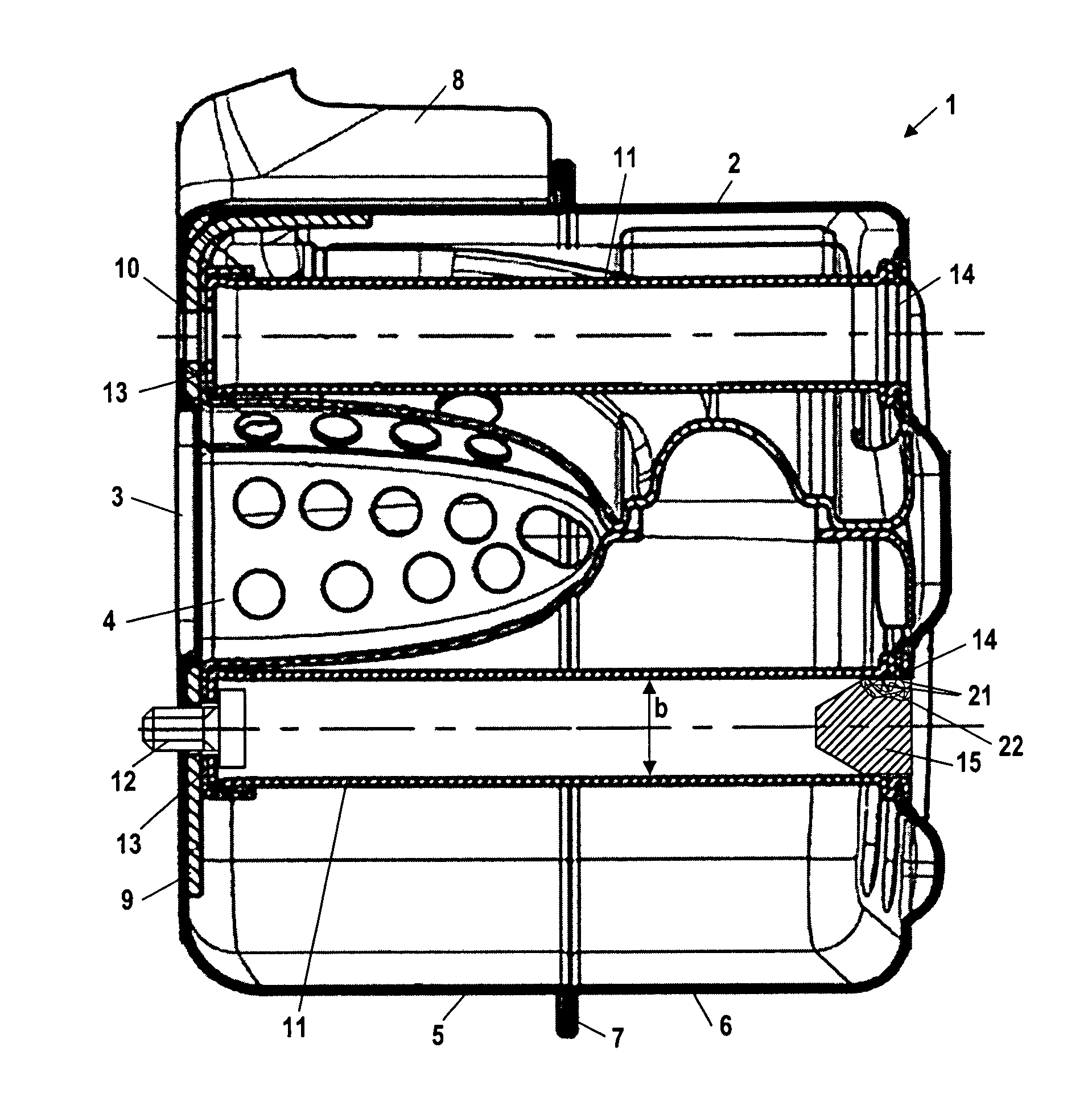
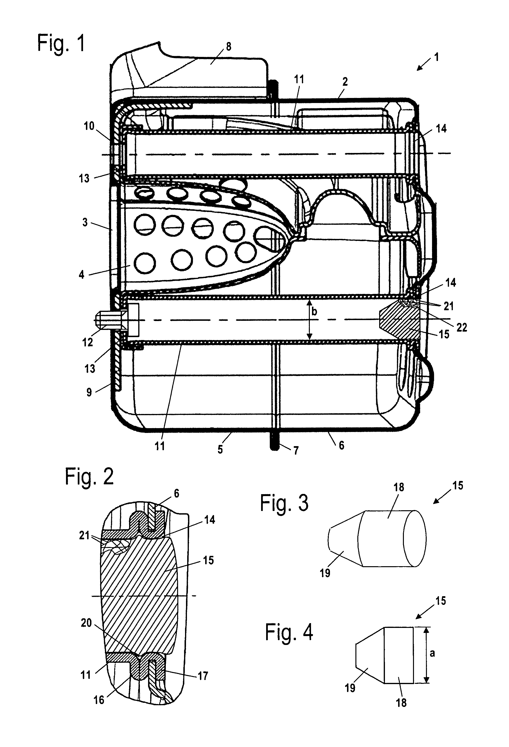
[0035]The exhaust-gas muffler 1 shown in FIG. 1 can, for example, be an exhaust-gas muffler in a portable handheld work apparatus such as a motor-driven chain saw, cutoff machine, brushcutter or the like. The exhaust-gas muffler 1 has a housing 2 into which an inlet 3 leads. The inlet 3 is connected to the outlet from an internal combustion engine, for example, a two-stroke engine or a mixture-lubricated four-stroke engine. In the interior of the housing 2, an exhaust-gas spray nozzle 4 is arranged next to the inlet 3 and this spray nozzle leads to a good attenuation of noise. The housing 2 is made up of a first half shell 5 and a second half shell 6 which are connected gas tight to each other at an edge 7. The first half shell 5 has the inlet 3 and is advantageously arranged facing toward an internal combustion engine. An outlet (not shown) leads from the housing 2 and is covered by an outlet cover or hood 8. A stiffening sheet metal member 9 is arranged in the interior of the firs...


PUM


Abstract

An exhaust-gas muffler (1) has a housing (2) through which at least one sleeve (11) projects. At one end, the sleeve (11) has an attachment opening (10) and at the opposite-lying end has an access opening (14). To avoid a contamination of the sleeve (11) during operation, a plug (15, 25, 35, 40, 45, 55) of a pressed metal wire is arranged in the access opening (14).

Description

CROSS REFERENCE TO RELATED APPLICATION[0001]This application claims priority of German patent application no. 10 2008 026 333.8, filed May 31, 2008, the entire content of which is incorporated herein by reference.FIELD OF THE INVENTION[0002]The invention relates to an exhaust-gas muffler having a housing through which at least one sleeve projects. The sleeve has an attachment opening at one end and, at the opposite-lying end, the sleeve has an access opening.BACKGROUND OF THE INVENTION[0003]For attaching an exhaust-gas muffler to the cylinder of an internal combustion engine it is known to provide one or several sleeves which project through the entire muffler housing and to arrange attachment elements at the base facing toward the cylinder, for example, attachment screws with which the exhaust-gas muffler can be fastened to the cylinder of the engine. The sleeves make the use of short attachment screws possible.[0004]Dirt can collect in the sleeves during operation of the engine. T...

Claims


Application Information

Patent Timeline
Patent Type & Authority Patents(United States)
IPC IPC(8): F01N1/08F16L17/00F16L15/08F01N13/18F01N13/10F01N5/00F01N1/16F16L27/04F16L19/00F16L17/06
CPCF01N13/1838F01N13/185F01N13/1855F01N13/1872F01N2590/06
Inventor BOHNAKER, EBERHARDHELFEN, REBEKKAMENZEL, JOHANNESZIMMERMANN, HELMUT
Owner ANDREAS STIHL AG & CO KG
Why Eureka
Try Eureka