Multiple rotor, wide blade, axial flow pump

a rotor and axial flow technology, applied in the direction of piston pumps, positive displacement liquid engines, liquid fuel engines, etc., can solve the problems of reducing the torque capacity and efficiency of motors, internal blood pumps also subject to anatomical compability design constraints,

Inactive Publication Date: 2011-07-05
HEARTWARE INC
View PDF107 Cites 99 Cited by
  • Summary
  • Abstract
  • Description
  • Claims
  • Application Information

AI Technical Summary

Benefits of technology

[0013]Accordingly, it can be seen that the need for a shaft between the rotors is eliminated. Also, a simplified housing may be used, as opposed to a split housing design that may be required for a traditional, multiple stage pump design. Since a multiple stage blood pump may permit diameter reduction relative to a comparable, single stage pump, this may further allow simplification of device implant procedure, and may significantly reduce patient surgical trauma.
[0051]The pump utilizes hydrodynamic thrust bearings for radial support and the magnetic bearings for axial support, primarily resulting in a system which has no mechanical wear, since no rubbing of solid surfaces takes place in a significant manner.

Problems solved by technology

Both of these approaches tend to reduce the motor torque capacity and efficiency, and most use mechanical rotor support involving abutting surfaces that move relative to each other in rotation.
Internally located blood pumps are also subject to anatomical compability design constraints, and the need for elimination of mechanical wear and associated failure modes in order to provide successful, long-term, implantable devices.

Method used


Image

  • Multiple rotor, wide blade, axial flow pump
  • Multiple rotor, wide blade, axial flow pump
  • Multiple rotor, wide blade, axial flow pump

Examples


Embodiment Construction

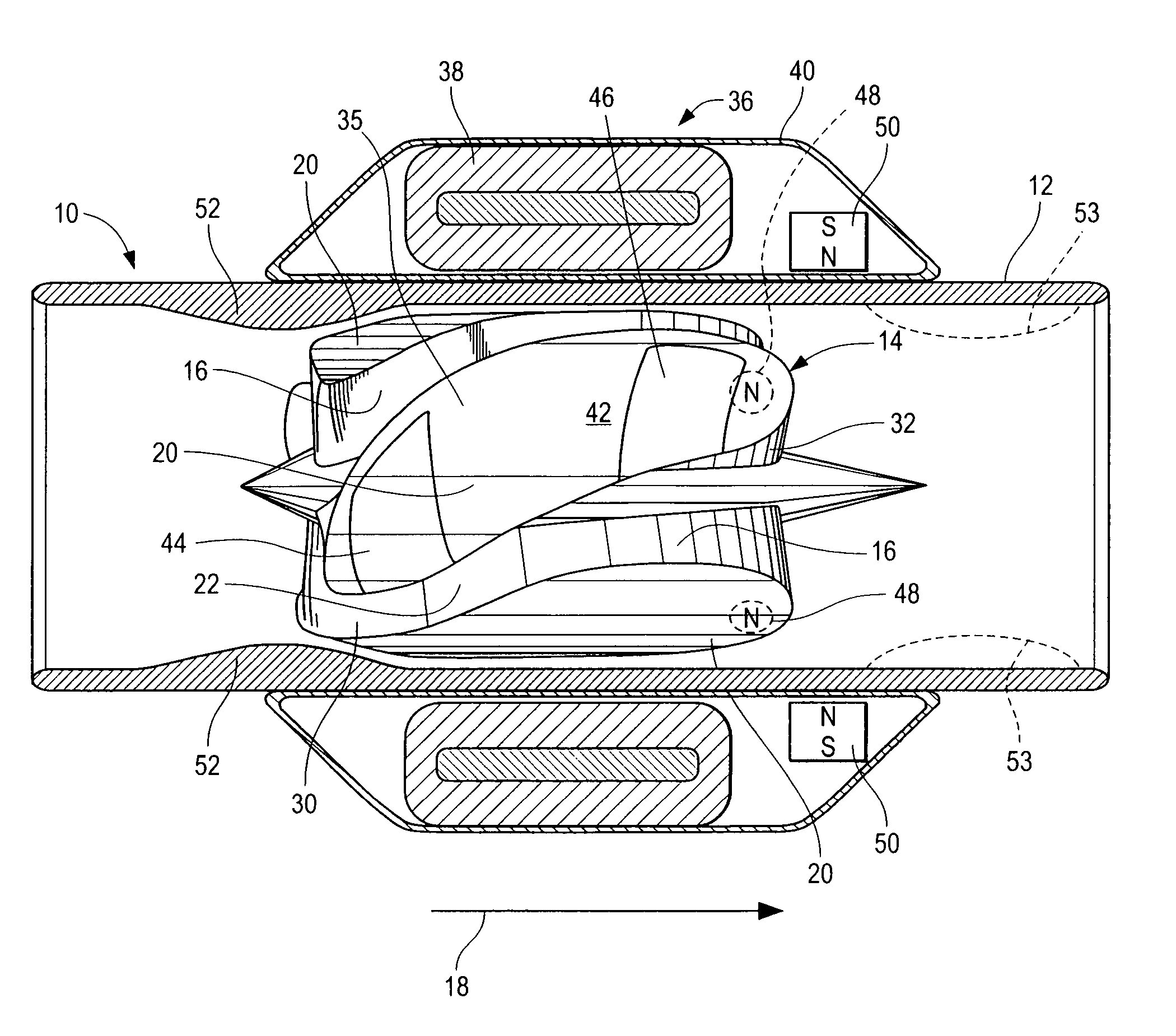
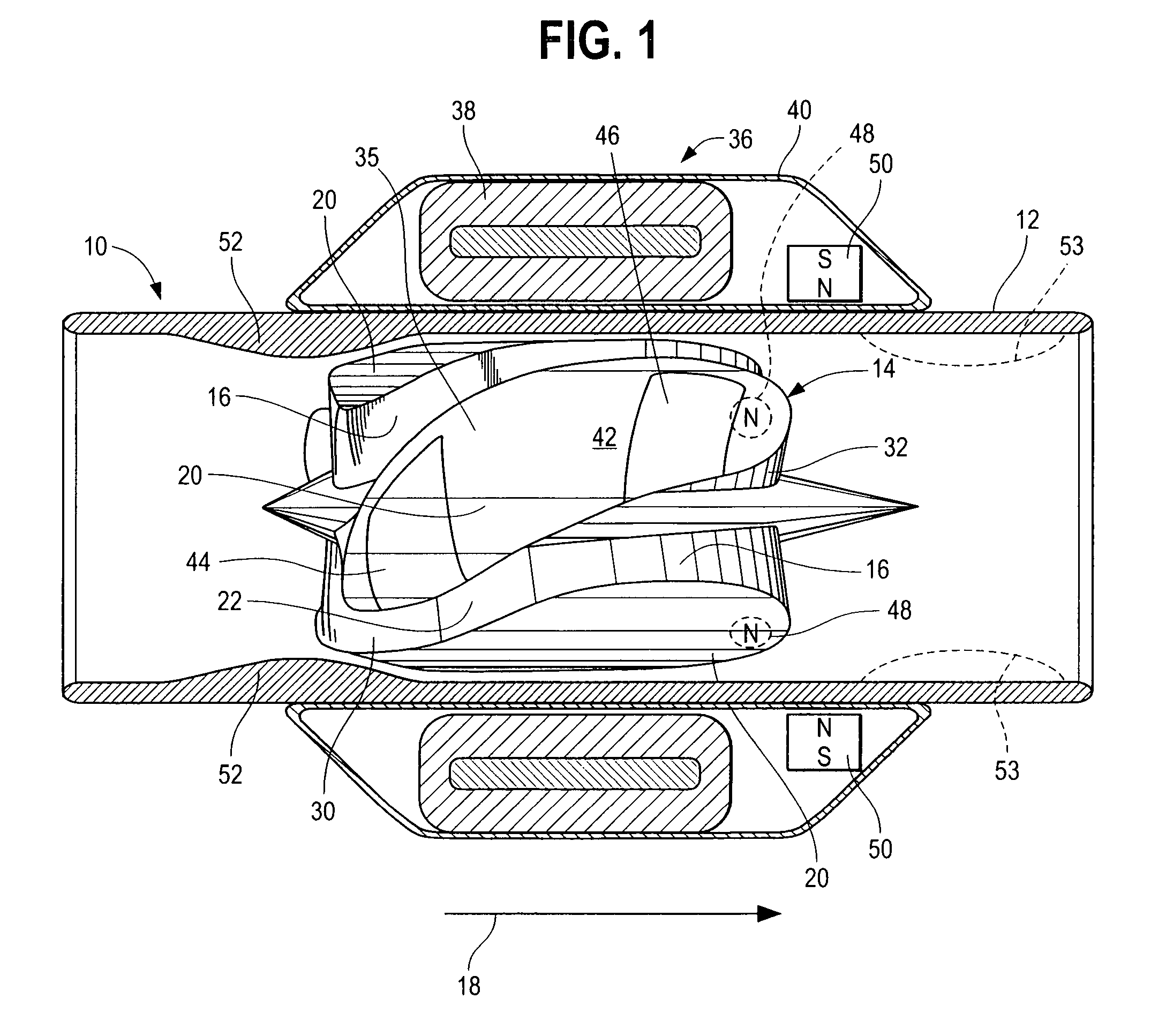
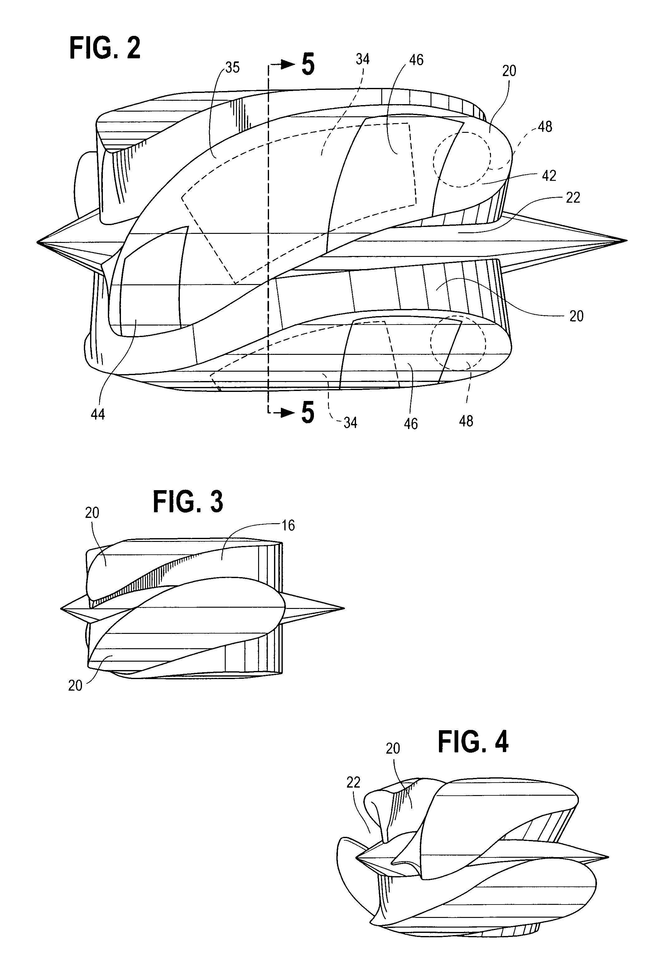
[0009]In accordance with this invention, a blood pump is provided which comprises a pump housing, a plurality of rotors positioned in the housing, each rotor comprising an impeller having a hydrodynamic surface for pumping blood, and a motor. The motor includes a plurality of magnetic poles carried by each impeller, to interact with motor stators, each stator including electrically conductive coils located adjacent to or within the housing.

[0010]By this invention, at least one of the rotors is adapted to rotate clockwise, and at least one of the rotors is adapted to rotor counterclockwise. Thus, it can be seen that the rotation of the respective rotors is generally independent of each other, and the rotors are preferably spaced from each other.

[0011]In some embodiments, the rotors are free of stationary, swirl suppressing blades positioned between them, since the need for such blades can be eliminated by the counterrotating characteristic of the respective rotors. Furthermore, in so...


PUM


Abstract

A blood pump comprises a pump housing; a plurality of rotors positioned in said housing, each rotor comprising an impeller having a hydrodynamic surface for pumping blood; and a motor including a plurality of magnetic poles carried by each impeller, having motor stators, each including electrically conductive coils located adjacent to or within the housing. At least one of the rotors is adopted to rotate clockwise, and at least one of rotors is adopted to rotate counterclockwise. By this means, stator or stationary blades between the rotors may not be needed.

Description

BACKGROUND OF THE INVENTION[0001]This discloses a modification of the pump devices disclosed in LaRose et al. U.S. patent application Ser. No. 11 / 003,810. The modification can also be used with other pumps as well.[0002]The known axial flow pumps for blood have the advantage of narrow width, when compared with radial flow pumps. Axial flow pumps typically have a cylindrical housing with an inlet at one end, an outlet at the opposite end, and a rotor within the housing which has impeller blades attached to the rotor. Thus, as the rotor rotates, the blades add work to the fluid, propelling the fluid through one end of the housing.[0003]A suspension system is provided to maintain the rotor in desired position within the housing, and a motor is provided to spin the rotor. Blood flows between the blades, being propelled through the pump by hydrodynamic forces transferred by the blade surfaces.[0004]The blood then leaves the pump, flowing parallel to the axis of rotation of the rotor. Typ...

Claims


Application Information

Patent Timeline
Patent Type & Authority Patents(United States)
IPC IPC(8): F04B35/04
CPCF04D3/02F04D29/181F04D13/0633F04D13/064A61M1/1013A61M1/1017A61M1/122A61M1/101A61M1/1015F04D29/669A61M60/824A61M60/422A61M60/148F04D13/0646A61M60/232A61M60/178A61M60/196A61M60/806A61M60/804A61M60/825
Inventor LAROSE, JEFFREY A.SHAMBAUGH, JR., CHARLES R.
Owner HEARTWARE INC
Why Eureka
Try Eureka