
Defect inspection method for a glass substrate for a mask blank, glass substrate for a mask blank, mask blank, exposure mask, method of producing a glass substrate for a mask blank, method of producing a mask blank, and method of producing an exposure mask

a technology of glass substrate and mask blank, which is applied in the direction of originals for photomechanical treatment, instruments, transportation and packaging, etc., to achieve the effect of improving transfer accuracy and reducing transmittan

Inactive Publication Date: 2011-07-05
HOYA CORP
View PDF12 Cites 0 Cited by
  • Summary
  • Abstract
  • Description
  • Claims
  • Application Information

AI Technical Summary

Benefits of technology

This approach allows for the successful detection of internal defects across the entire glass substrate, including those near the principal surface, preventing transfer pattern defects and enhancing the accuracy of pattern transfer during semiconductor production.

Problems solved by technology

However, even if the exposure mask is produced by the use of the synthetic silica glass substrate and the glass substrate for a mask blank which are judged by the above-mentioned defect inspection apparatus to have no internal defect, a transfer pattern defect derived from the glass substrate (which will later be described) may be caused during pattern transfer in which a mask pattern of the exposure mask is transferred to a semiconductor substrate by the use of an ArF excimer laser as the exposure light.

Method used


Image

  • Defect inspection method for a glass substrate for a mask blank, glass substrate for a mask blank, mask blank, exposure mask, method of producing a glass substrate for a mask blank, method of producing a mask blank, and method of producing an exposure mask
  • Defect inspection method for a glass substrate for a mask blank, glass substrate for a mask blank, mask blank, exposure mask, method of producing a glass substrate for a mask blank, method of producing a mask blank, and method of producing an exposure mask
  • Defect inspection method for a glass substrate for a mask blank, glass substrate for a mask blank, mask blank, exposure mask, method of producing a glass substrate for a mask blank, method of producing a mask blank, and method of producing an exposure mask

Examples


Embodiment Construction

[0030]Now, description will be made of a preferred embodiment of this invention with reference to the drawing. In the following description, an ArF excimer laser light (having an exposure wavelength of 193 nm) having an exposure wavelength of 200 nm or less is used as an exposure light.

[0031](A) Method of Producing a Glass Substrate for a Mask Blank

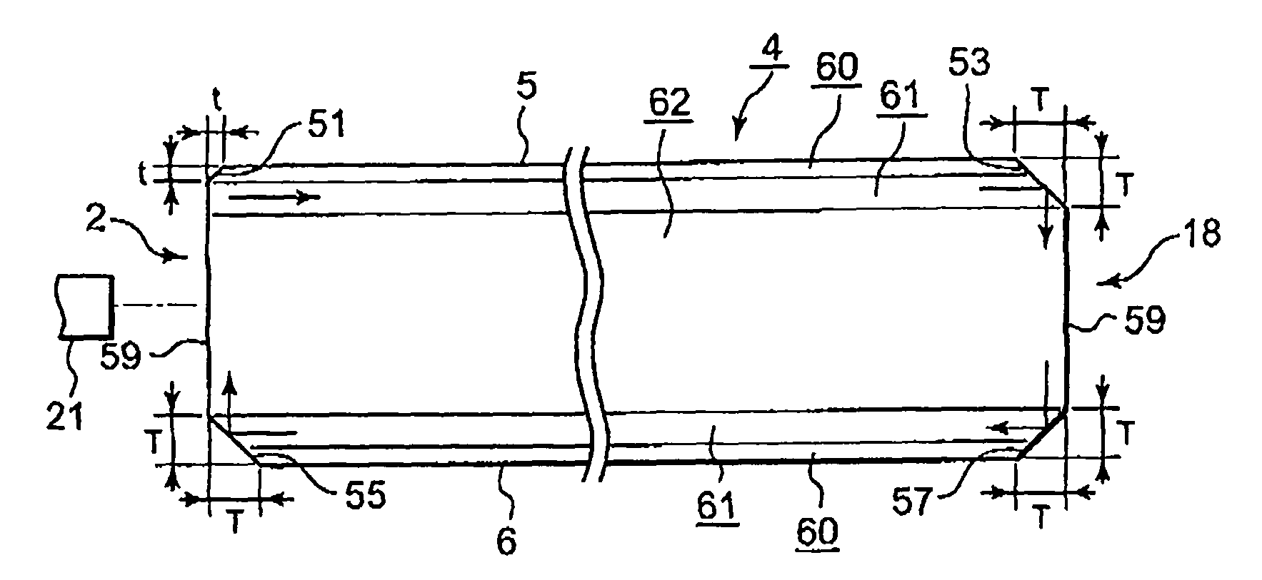
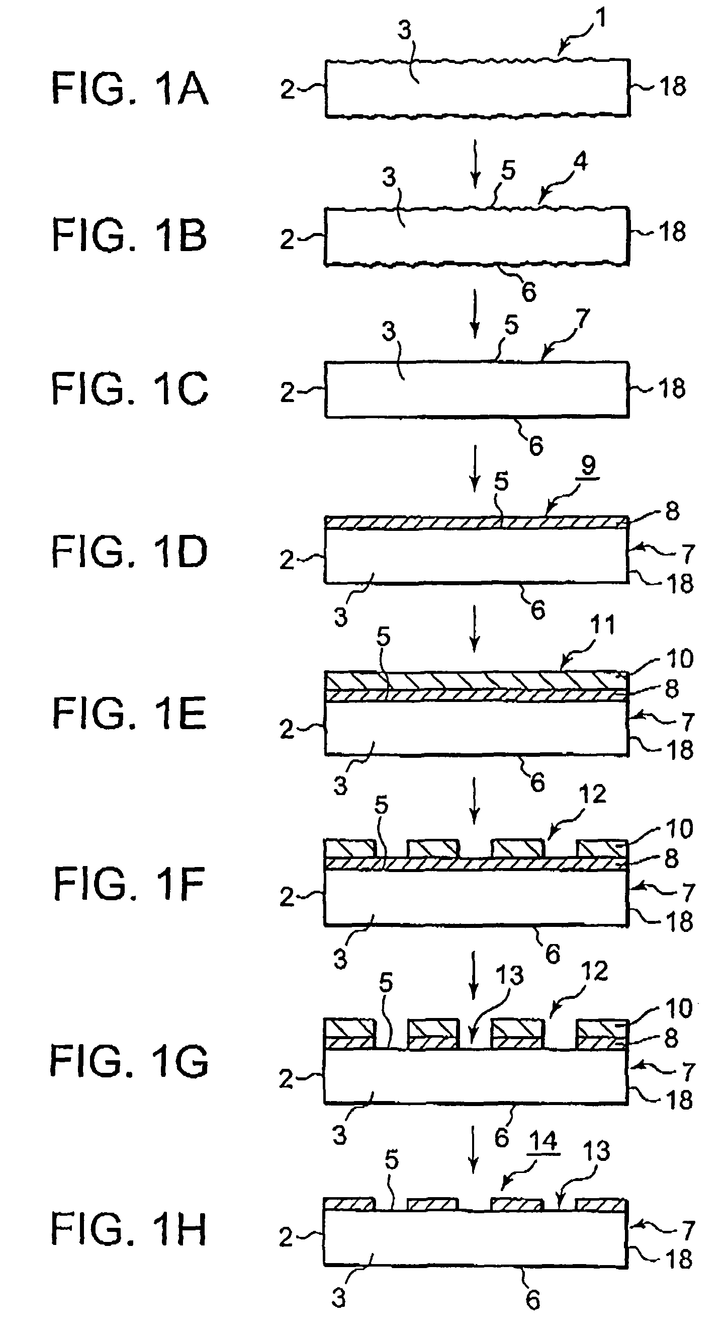
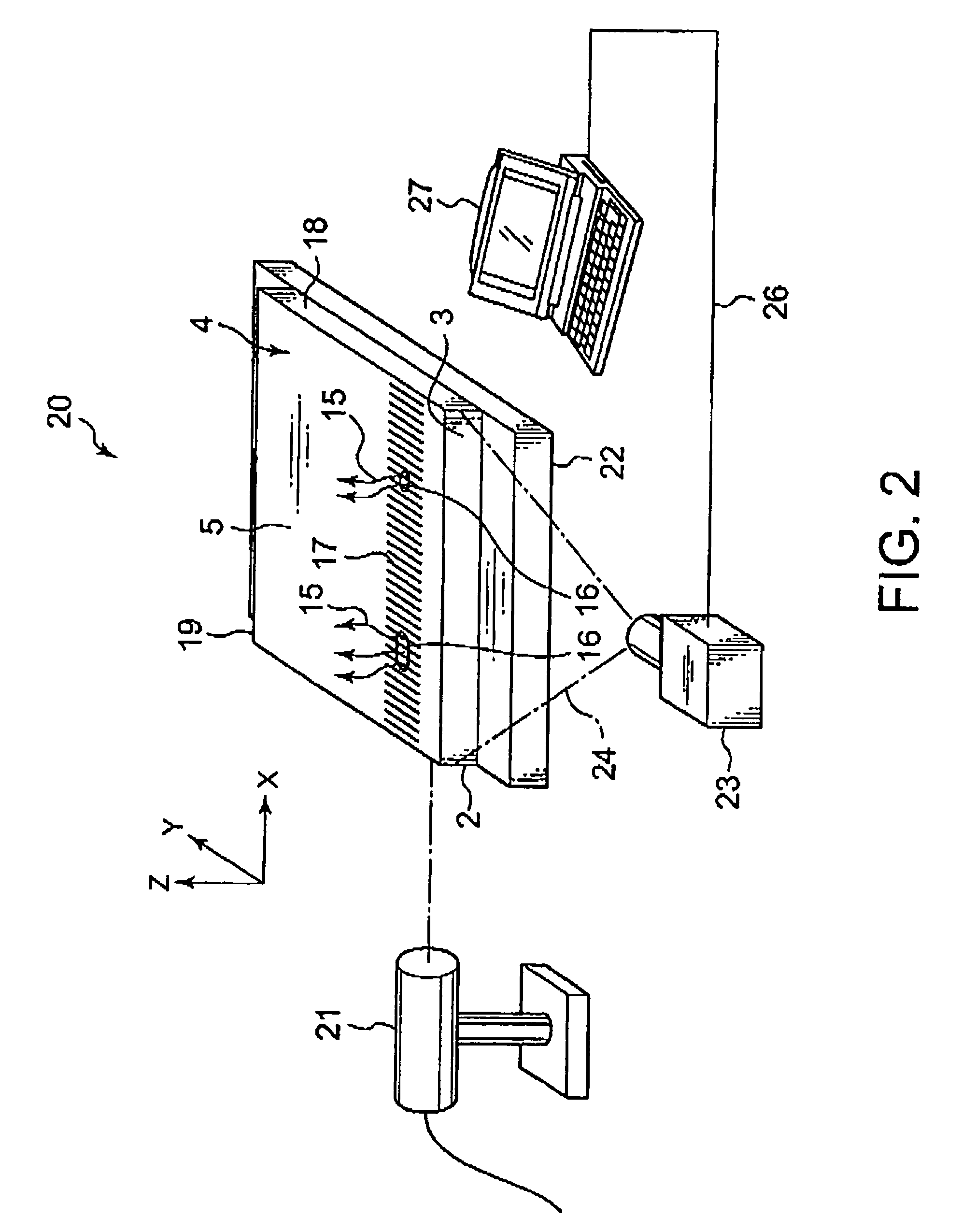
[0032]Referring to FIG. 1, a synthetic silica glass ingot is prepared according to the production process disclosed in Japanese Unexamined Patent Application Publications (JP-A) Nos. H8-31723 or 2003-81654. By cutting the synthetic silica glass ingot, a synthetic silica glass plate 1 having a dimension of about 152.4 mm×about 152.4 mm×about 6.85 mm is obtained (FIG. 1A). The synthetic silica glass plate 1 has principal surfaces 5 and 6 opposite to each other. The synthetic silica glass plate 1 is subjected to chamfering. The synthetic silica glass plate 1 also has an end face 2 through which a short-wavelength light having a wavelength of...


PUM

PropertyMeasurementUnit
wavelengthaaaaaaaaaa
depthaaaaaaaaaa
exposure wavelengthaaaaaaaaaa

Abstract

On inspecting a glass substrate for a mask blank which substrate has surfaces including one end face, the glass substrate is prepared to have the one end face which has a chamfered surface and a remaining surface serving as a side surface. The chamfered surface of the one end face is smaller in width than a chamfered surface of an opposite end face of the glass substrate. A short-wavelength light having a wavelength of 200 nm or less is introduced into the side surface of the one end face. From either the one end face or a different surface of the surfaces of the glass substrate, a long-wavelength light is received which is longer in wavelength than the short-wavelength light and which is generated by an internal defect of the glass substrate in response to the short-wavelength light. The internal defect is detected with reference to the long-wavelength light.

Description

[0001]This application claims priority to prior Japanese patent application JP 2005-171153, the disclosure of which is incorporated herein by reference.BACKGROUND OF THE INVENTION[0002]This invention relates to a defect inspection method of inspecting internal defects of a glass substrate for a mask blank, a glass substrate for a mask blank to be inspected by the defect inspection method, a mask blank produced from the glass substrate, an exposure mask produced from the mask blank, a method of producing a glass substrate for a mask blank after inspecting internal defects of the glass substrate, a method of producing a mask blank by the use of the glass substrate, and a method of producing an exposure mask by the use of the mask blank.[0003]In recent years, following a miniaturization of a semiconductor device, an exposure light having a shorter wavelength is used in the photolithography. For example, an ArF excimer laser (having an exposure wavelength of 193 nm) and a F2 excimer las...

Claims


Application Information

Patent Timeline
Patent Type & Authority Patents(United States)
IPC IPC(8): B32B17/06G03F1/50G03F1/60G03F1/84
CPCG01N21/958G03F1/84G01N2021/646Y10T428/24
Inventor TANABE, MASARU
Owner HOYA CORP
Learn More