
Apparatus for equalizing decision feedback based on channel properties change and method therefor

a decision-based feedback and channel technology, applied in the field of channel equalization techniques, can solve problems such as obstacles in obtaining required data, data transmission affected by a variety of channel distortions, interference occurred in adjacent symbols, etc., to improve convergence speed and stability of digital filter units, reduce decision errors, and reduce complexity

Inactive Publication Date: 2011-07-05
ELECTRONICS & TELECOMM RES INST
View PDF18 Cites 5 Cited by
  • Summary
  • Abstract
  • Description
  • Claims
  • Application Information

AI Technical Summary

Benefits of technology

The present invention relates to a method and apparatus for equalizing channel distortion in terrestrial digital broadcasting receivers. The technical effect of the invention is to decrease decision error in the symbol detector, which can be caused by poor channel conditions and distortion factors. The invention achieves this by mildly changing the channel characteristic with a matched filter, approximating the channel characteristic using a noncausal filter, and employing a trellis decoder with reduced complexity. The invention also addresses the issue of training sequence insertion failing to open the eye diagram of the equalization device output, which can lead to high decision error. The invention proposes a method of reducing decision error even during a data interval with no training sequence, which is important for minimizing any error propagation problem in the feedback loop of the equalizer.

Problems solved by technology

In digital communication systems, since data is generally transmitted over a limited band, interference is occurred in adjacent symbols due to a time dispersion effect that allows pulse energy of symbols to be dispersed into adjacent symbol pulses.
Besides, data transmitted is affected by a variety of channel distortions.
These phenomenons cause InterSymbol Interference (ISI), implying that transmission symbols affect adjacent symbols in digital communication systems, which becomes a great obstacle in obtaining required data.
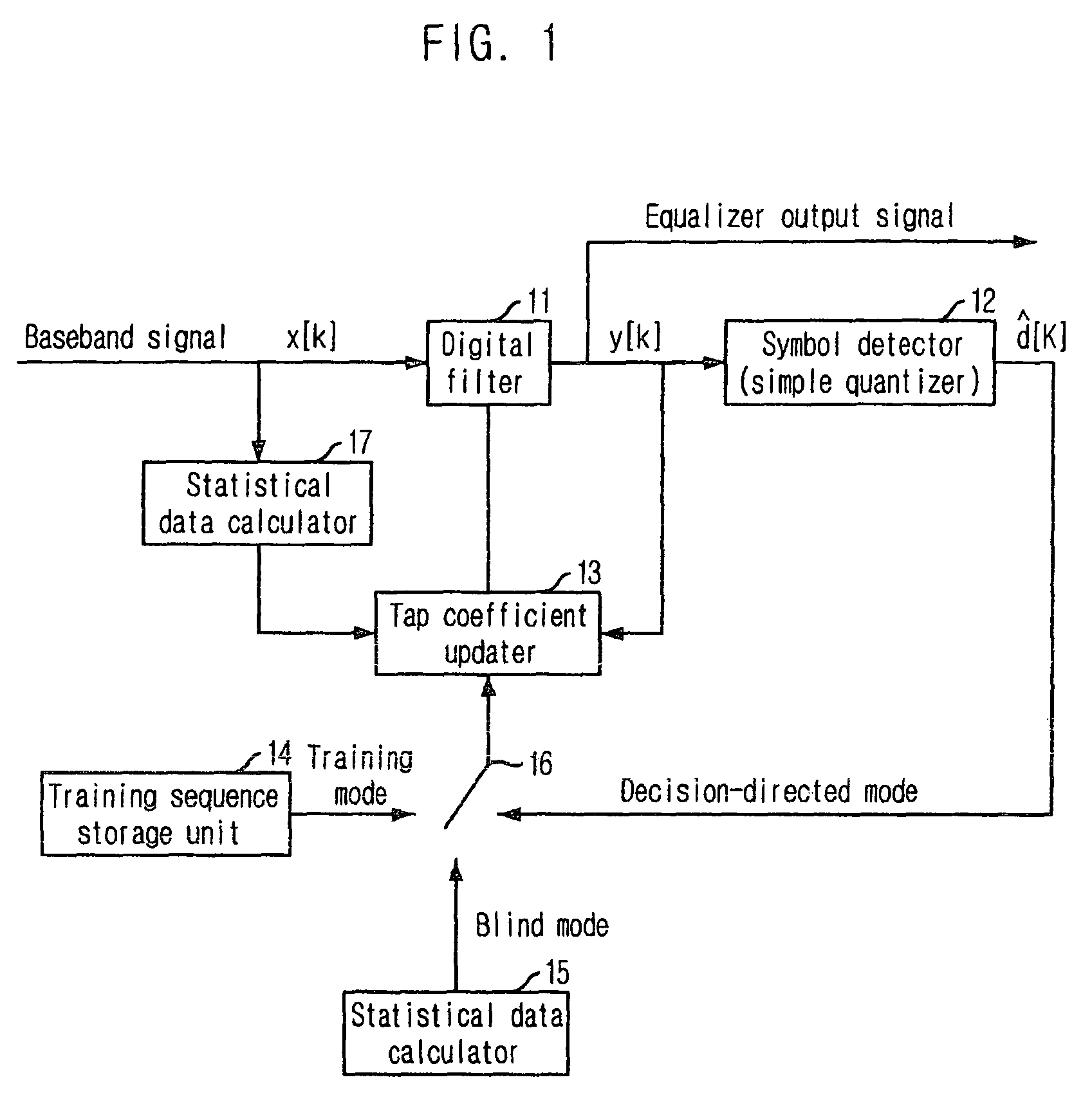
However, there exist many cases that it fails to open the eye diagram of the filter output since the inserted training sequence is short under a multi-path environment with a long ghost.
Further, under a poor multi-path environment with insufficient tap coefficients of the filter in length for their convergence although the training sequence is existed, time-variable channel varied according to time, long ghost, or ghost with large signal level, there are many cases that it fails to open the eye diagram of the filter output.
If the eye diagram is not open, there is a very high possibility that raises decision error in the symbol detector.
This brings about an error propagation problem that allows error decision to be accumulated through the feedback loop of the DFE device.
It is not very efficient to apply the Viterbi decoder with such a decoding delay value to actual systems.
The method of increasing the tap number of the feedforward filter is known to be inefficient and performance improvement is lowered compared with an increased amount of tap number.
The channel equalization method suggested by Richard Citta has a very high degree of complexity since it provides a channel matched filter using over-sampled data and employs a fractionally-spaced equalization device.
Furthermore, since such a method utilizes a simple quantizer (slicer) as a symbol detector, there may be occurred an error propagation problem by decision error.
This method improves stability of convergence but has a disadvantage in that the length of a pre ghost is long due to use of the channel matched filter, thereby causing a residual mean square error after convergence to be larger than a case with no channel matched filter rather.

Method used


Image

  • Apparatus for equalizing decision feedback based on channel properties change and method therefor
  • Apparatus for equalizing decision feedback based on channel properties change and method therefor
  • Apparatus for equalizing decision feedback based on channel properties change and method therefor

Examples


Embodiment Construction

The above-mentioned objectives, features, and advantages will be more apparent by the following detailed description in association with the accompanying drawings; and thus, the invention will be readily conceived by those skilled in the art to which the invention pertains. Further, in the following description, well-known arts will not be described in detail if it seems that they could obscure the invention in unnecessary detail. Hereinafter, preferred embodiments of the present invention will be set forth in detail with reference to the accompanying drawings.

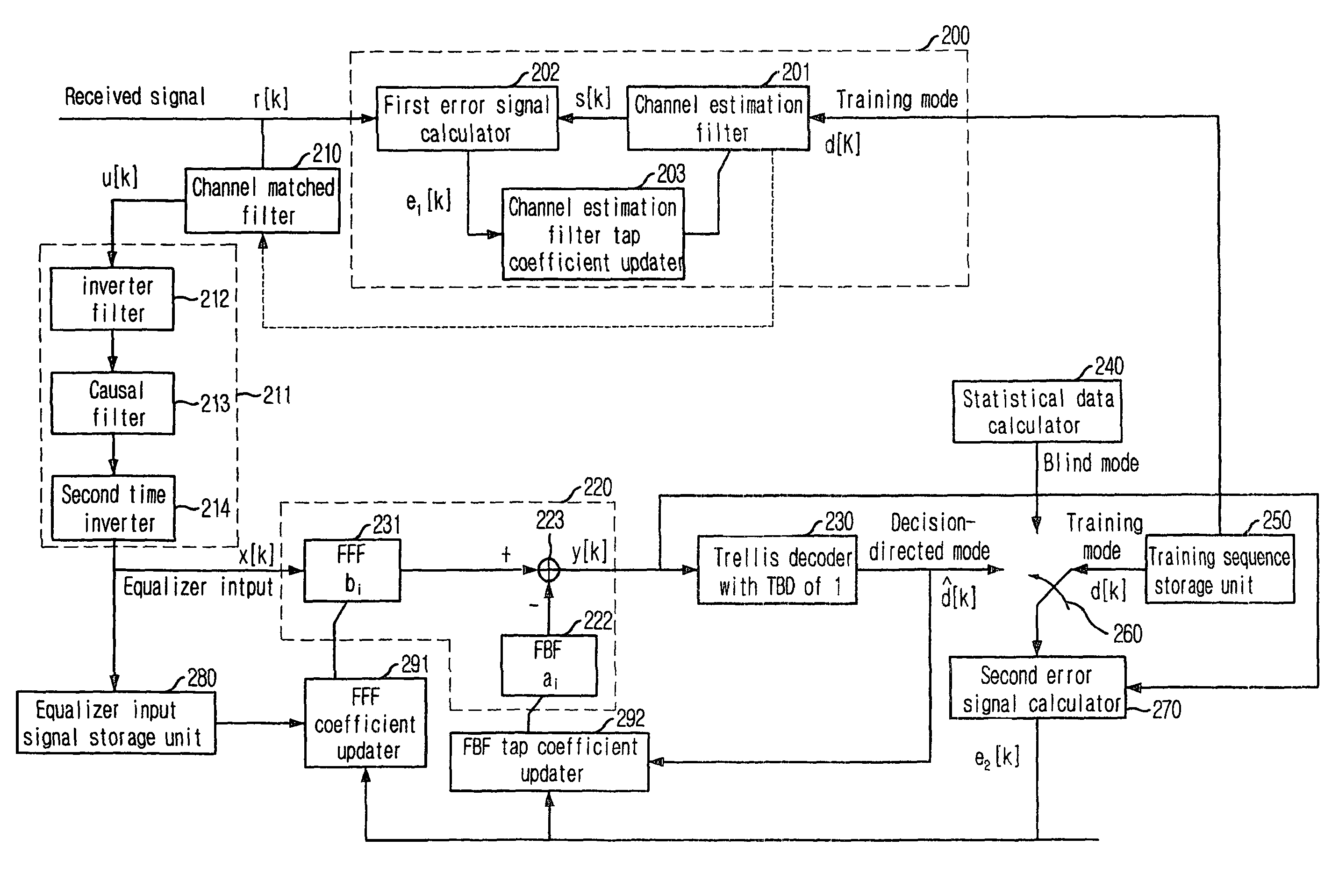
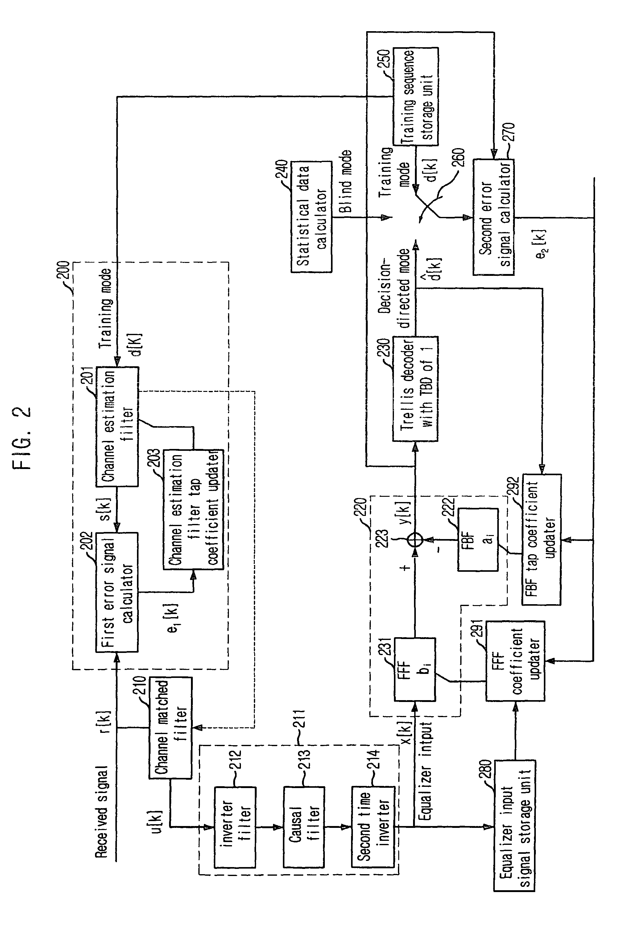
In the following embodiments, a description will be provided as illustration on a case that the present invention is applied to an 8-Vestigial SideBand (VSB) system that is American-type terrestrial TV standard; but it should be noted that the present invention is not limited to such an illustration.

FIG. 2 is a block diagram illustrating a configuration of a DFE apparatus in accordance with an embodiment of the present inventi...


PUM


Abstract

A decision feedback equalization apparatus includes a channel estimation unit estimating a channel on received signal based on the received signal and a training sequence; a channel matched filter maximizing SNR from the channel estimated by the channel estimation unit changing channel characteristics of the received signal; a noncausal filter approximating the changed channel; an equalizer input signal storage unit storing received symbols passed through the channel matched and the noncausal filters; a channel equalization unit performing a decision feedback equalization; a Trellis decoder detecting symbol from a channel-equalized signal; a mode selection unit selecting a specific mode; an error signal calculator comparing an output signal of the selected mode with an output signal of the channel equalization unit to calculate an error signal; and a tap coefficient updater updating tap coefficients to the channel equalization unit, an output signal from the storage unit, and an output signal from the Trellis decoder.

Description

TECHNICAL FIELDThe present invention relates to channel equalization techniques used in terrestrial digital broadcasting reception systems, and more particularly, to a decision feedback equalization apparatus and method capable of decreasing decision error. This is achieved by mildly changing channel characteristic of received signal distorted by poor channel using a channel matched filter, approximating channel characteristic changed by the channel matched filter from nonminimum phase channel to minimum phase channel using a noncausal filter, and adopting a trellis decoder whose Trace Back Depth (TBD) is 1 and degree of complexity is reduced as a symbol detector of the equalization apparatus.BACKGROUND ARTIn digital communication systems, since data is generally transmitted over a limited band, interference is occurred in adjacent symbols due to a time dispersion effect that allows pulse energy of symbols to be dispersed into adjacent symbol pulses. Besides, data transmitted is aff...

Claims


Application Information

Patent Timeline
Patent Type & Authority Patents(United States)
IPC IPC(8): H03H7/30H03H7/40H03K5/159
CPCH04B3/04H04L25/0212H04L25/03057H04L2025/0349H04L2025/03617
Inventor PARK, SUNG-IKKIM, SEUNG-WONLEE, SOO-INKIM, HYOUNG-NAMLEE, YOU-SEOK
Owner ELECTRONICS & TELECOMM RES INST
Learn More