Device for depositing a coating on an internal surface of a container

a technology for a container and a coating, which is applied in the direction of chemical vapor deposition coating, decorative surface effects, decorative arts, etc., can solve the problems of difficult to precisely control the ignition of the plasma and its stability, non-uniform deposition of the coating, and incurring risks, so as to improve the blocking of electromagnetic wave propagation and reduce the amount of electromagnetic energy

Inactive Publication Date: 2011-07-12
SIDEL PARTICIPATIONS SAS
View PDF17 Cites 38 Cited by
  • Summary
  • Abstract
  • Description
  • Claims
  • Application Information

AI Technical Summary

Benefits of technology

[0015]In this way, because the end of the injection tube corresponds to an antinode of the electromagnetic wave propagated along this tube, and because of the placement of this end between one half and one quarter of the total height of the container, ignition of a stable plasma is facilitated since the end of the injector corresponds to a point of maximum electromagnetic intensity for a given wavelength and with a uniform distribution of the gases in the container.
[0033]To reduce the amount of electromagnetic energy that is not blocked by the circular plate of the short-circuit provided according to the invention, a second circular plate is fixed radially to the injection tube upstream of the circular plate.

Problems solved by technology

However, the plasma coating process in a device as described above, although operating correctly, suffers from certain risks that may result in nonuniform deposition of the coating.
This is because it is often difficult to precisely control the ignition of the plasma and its stability, an unstable plasma incurring risks of forming a nonuniform coating on the internal wall of the container.
If a luminous instability is detected, it is therefore considered that the plasma was unstable and therefore, arbitrarily, that the coating was not deposited correctly.
Thus, if the deposition of the coating takes place by means of an installation for internally coating several thousand containers per hour, it is necessary to reduce as far as possible the percentage of containers that are not correctly coated, which represent scrap and possibly amounting to several hundred containers per day.
Moreover, when the electromagnetic waves are transmitted into the cavity, they are reflected by the injection tube and tend to rise up along the latter toward the center of the treatment device, incurring risks of malfunction of the device and loss of electromagnetic energy that can be used in the treatment cavity, hence risks of plasma instability.

Method used


Image

  • Device for depositing a coating on an internal surface of a container
  • Device for depositing a coating on an internal surface of a container
  • Device for depositing a coating on an internal surface of a container

Examples


Embodiment Construction

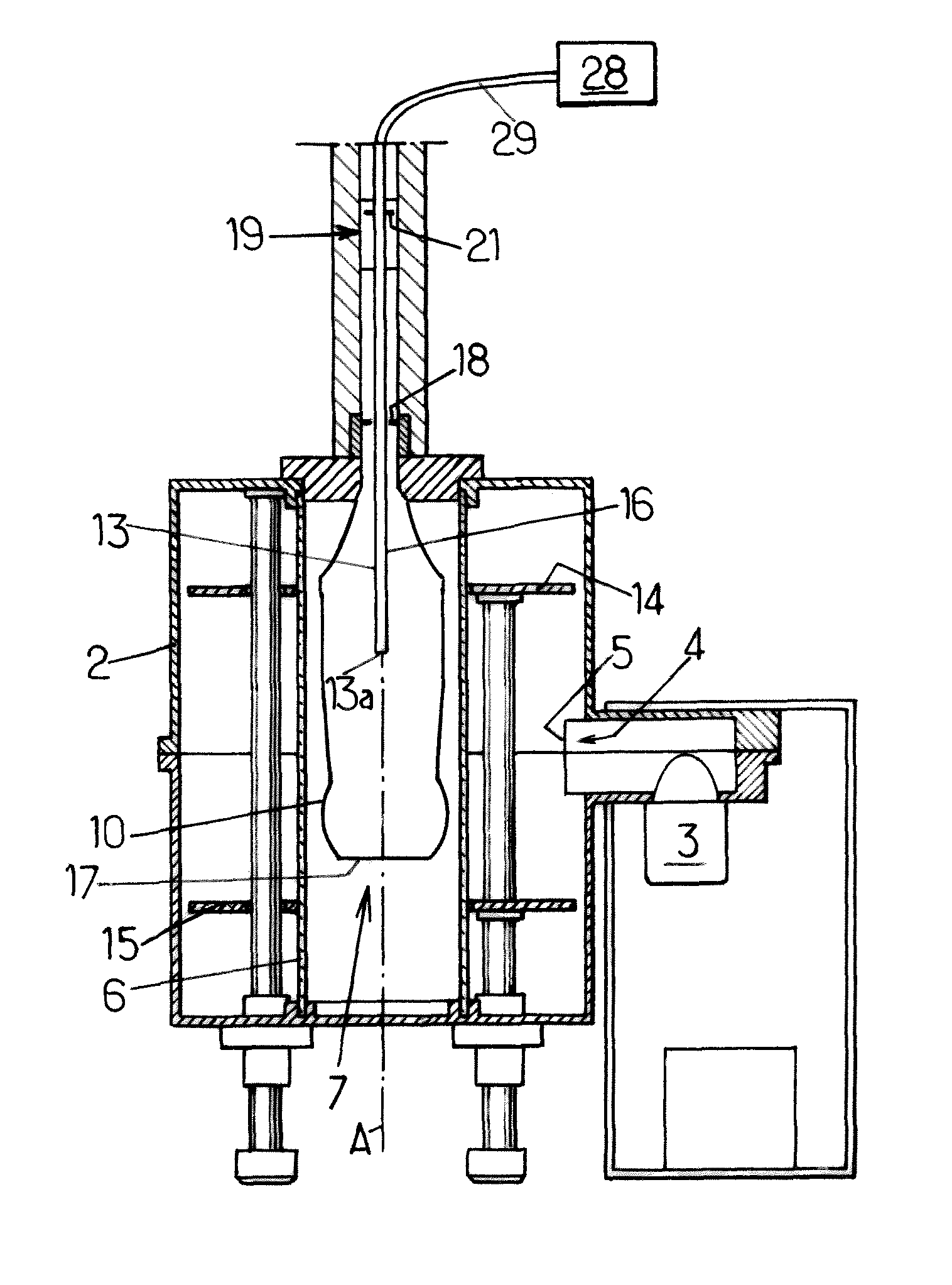
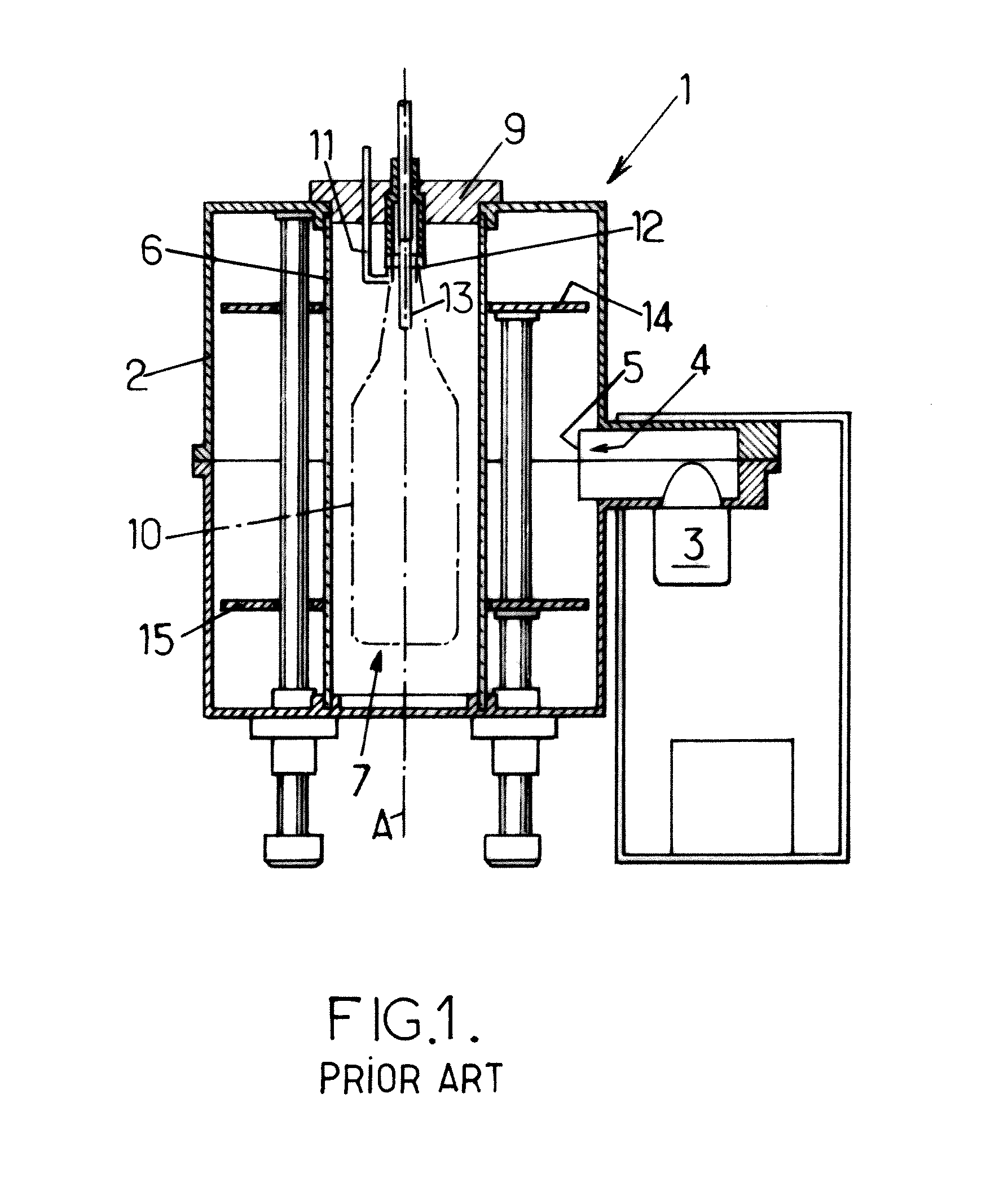
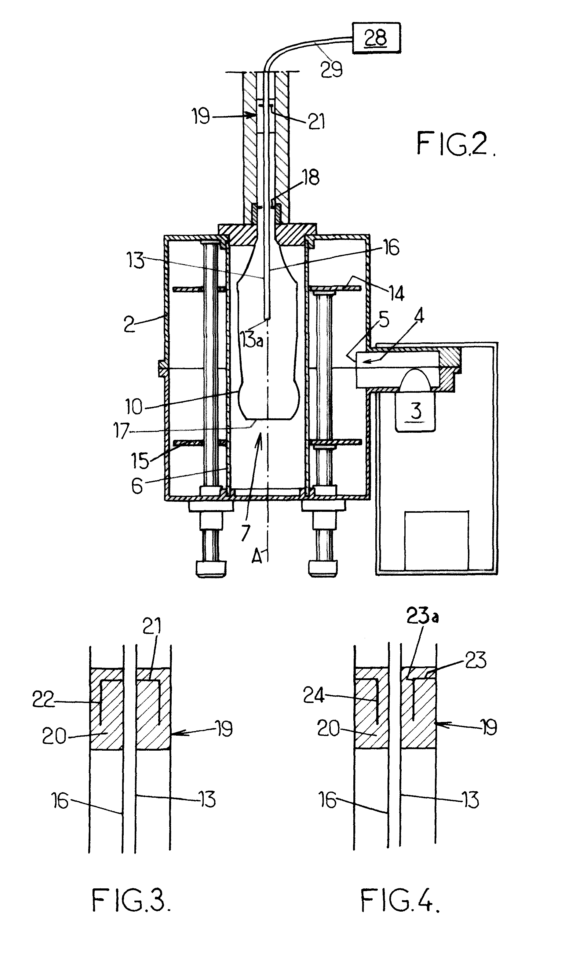
[0042]As already described, FIG. 1 is a schematic view of a device for depositing a coating on an internal surface of a thermoplastic container 10, of the type in which the deposition is carried out by means of a low-pressure plasma created inside the container by excitation of a precursor gas by microwave-type UHF electromagnetic waves, and of the type in which the container 10 is placed in a cavity 2 made of conducting material into which the microwaves are introduced, said device comprising: a UHF electromagnetic wave generator 3; an electromagnetic waveguide 4, for connecting said generator 3 to a window 5 in the side wall of the cavity 2; means for injecting the precursor gas; means for pumping down the cavity 2 and the internal volume of the container 10; and an internal envelope 6, coaxial with the cavity 2 and with at least one central field generated in the cavity 2, said envelope being substantially transparent to the electromagnetic waves, for example made of quartz, and ...


PUM

PropertyMeasurementUnit
voltageaaaaaaaaaa
voltageaaaaaaaaaa
envelope frequencyaaaaaaaaaa

Abstract

Device for depositing a coating on an internal surface of a container, of the type in which the deposition is carried out by means of a low-pressure plasma created inside the container by excitation of a precursor gas by microwave-type electromagnetic waves. An injection tube is provided that dips into the container to a length of between one quarter and one half of the total height of the container in question, between the top and the bottom of the container said length of the injection tube constituting a longitudinal antenna capable of picking up a UHF electromagnetic wave generated by said generator and of propagating the HT ignition signal, a UHF short-circuit in the form of a plate being provided on the injection tube in such a way that the face of said plate on the cavity side defines a point of zero amplitude of the electromagnetic wave propagating along said injection tube, the length between said short-circuit and the free end of said injection tube corresponding to an odd number of quarter-wavelengths so as to obtain a maximum amplitude, that is to say an antinode, at the free end of the injection tube.

Description

TECHNICAL FIELD[0001]The present invention relates to a device for depositing a coating on an internal surface of a container made of a thermoplastic, of the type in which the deposition is carried out by means of a low-pressure plasma, which is created inside the container by excitation of a precursor gas by electromagnetic waves of microwave type, and of the type in which the container is placed in an enclosure made of conducting material into which the microwaves are introduced, said device comprising: a) an electromagnetic wave generator; b) an electromagnetic waveguide for connecting the generator to a window in the side wall of the enclosure, allowing at least one central field to be generated in this enclosure; c) means for injecting the precursor gas; d) means for pumping down the enclosure and the internal volume of the container; and e) an internal envelope, coaxial with the enclosure and substantially transparent to the electromagnetic waves, for example made of quartz, a...

Claims


Application Information

Patent Timeline
Patent Type & Authority Patents(United States)
IPC IPC(8): C23C16/00H01L21/306C03C15/00C03C25/68C23F1/00
CPCC23C16/045C23C16/511H01J37/32192H01J37/3222B05D1/62B05D7/227
Inventor RIUS, JEAN-MICHELCHOMEL, NICOLASDUCLOS, YVES-ALBAN
Owner SIDEL PARTICIPATIONS SAS
Why Eureka
Try Eureka