Carbon dioxide capture from a cement manufacturing process

a technology of carbon dioxide and cement manufacturing, which is applied in cement production, mechanical equipment, machines/engines, etc., can solve the problems that fuel costs are a significant factor in the final cost of the product, and achieve the effects of reducing the presence of non-hydrating phases, and reducing the number of hydration phases

Active Publication Date: 2011-07-12
SAVANNAH RIVER NUCLEAR SOLUTIONS +1
View PDF6 Cites 5 Cited by
  • Summary
  • Abstract
  • Description
  • Claims
  • Application Information

AI Technical Summary

Benefits of technology

It is yet another aspect of at least one embodiment of the present invention to control the addition points for carbonate oxides (CaO / MgO) in order to obtain increased yields of hydrating belite and alite, the addition points within a process further allowing a control of the ratio of belite to alite in the final product. Such controls allow cement manufacturers to control early and late hydration strength, minimize the presence of non-hydrating phases in a final product, and allow for higher beta-belite in the final product thereby increasing late cure strength and allowing lower formation temperatures to be used in the cement manufacturing process.

Problems solved by technology

Given the high temperatures required for the process, fuel costs constitute a significant factor in the ultimate cost of the product.

Method used


Image

  • Carbon dioxide capture from a cement manufacturing process
  • Carbon dioxide capture from a cement manufacturing process
  • Carbon dioxide capture from a cement manufacturing process

Examples


example 1

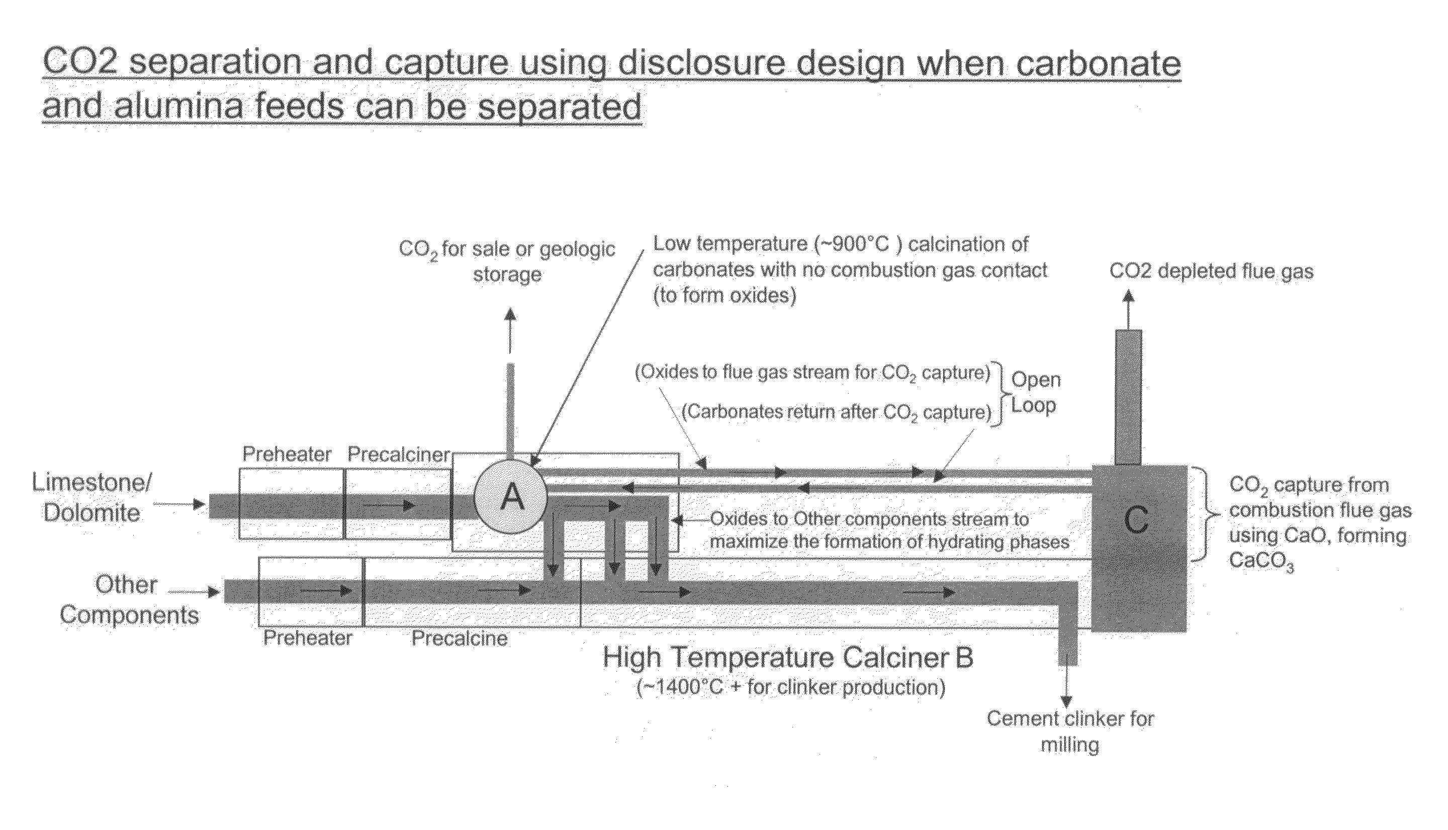
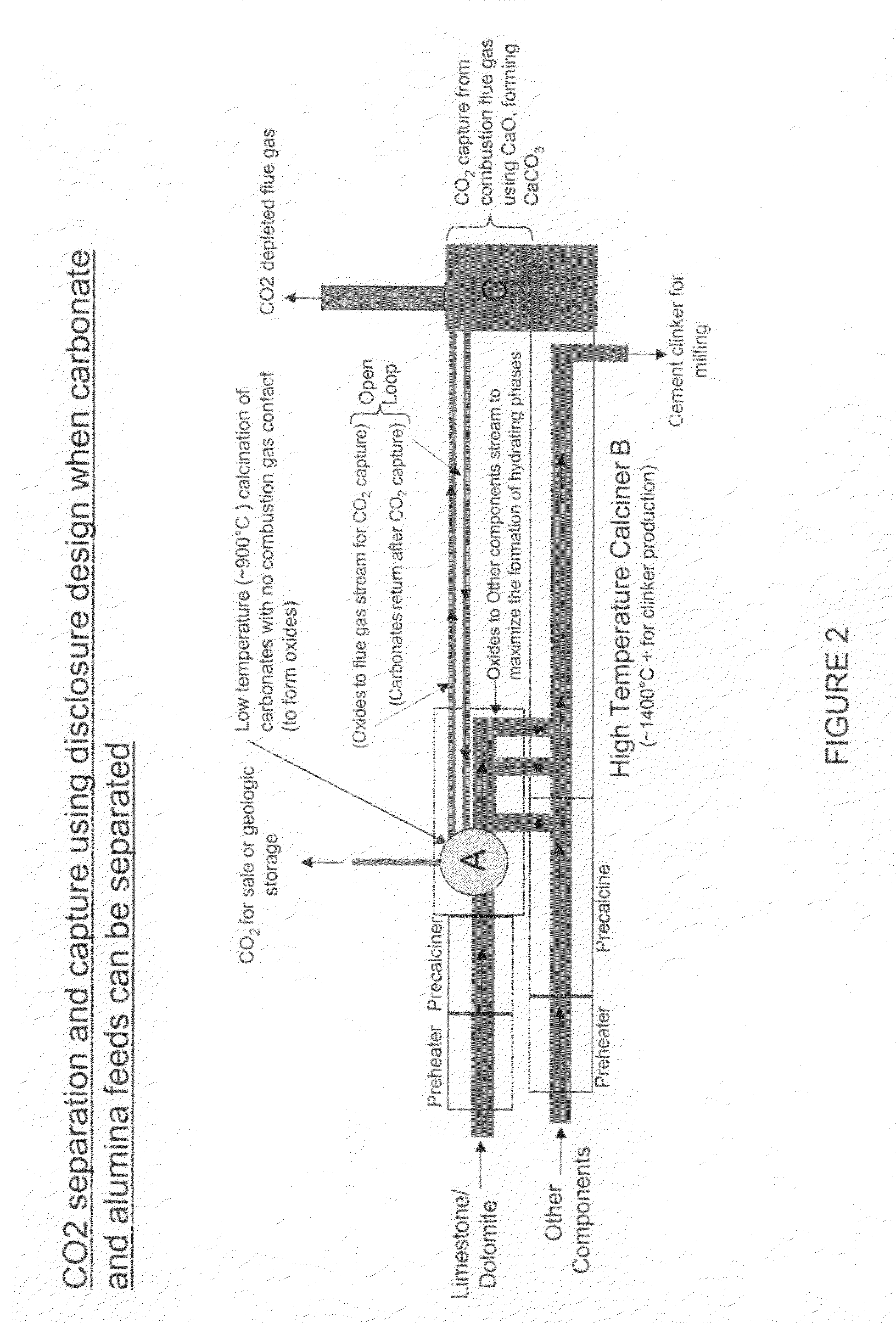
As seen in reference to FIG. 2, limestone / dolomite may be segregated from other components of clinker manufacturing and fed into a pre-heater and a precalciner segment during which time the limestone / dolomite undergoes drying and preheating to approximately 600° C. Thereafter, the heated limestone / dolomite is fed into the calciner (A) which raises the temperature of the feed to approximately 1050° C. for discharge to the remaining portion of the cement making process. Between 600° C. and 1050° C. the majority of the limestone / dolomite (CaCO3 / CaMg(CO3)2) decomposes to CaO / MgO with a release of CO2, which is captured and removed from calciner (A) prior to discharge to the high temperature calciner (B). As illustrated in FIG. 2, a fraction of the CaO / MgO maybe conveyed in an open loop manner to a separate location for interaction with combustion flue gas forming CaCO3 / CaMgCO3 at location (C) which is then returned to the calciner (A) for subsequent stripping of CO2. From the calciner (...

example 2

As seen in reference to FIG. 3, a process may be provided in which the clinker constituents cannot be easily separated into a separate limestone / dolomite phase. In this scenario, the pre-heater and pre-calciner are operated at temperatures similar to those described in reference to Example 1. The calciner (A) provides for no combustion gas contact with the material feed such that the CO2 evolved in the calciner is of a sufficiently clean form that it may be captured for sale and / or geologic storage. A portion of the CaO / MgO which is produced in calciner (A) is used to scrub the combustion flue gas at location (C) from the clinker production so as to remove CO2 from the flue gas, thereby forming CaCO3 / CaMg(CO3)2. The CaCO3 / CaMg(CO3)2 feed is thereafter introduced into the calciner (A) resulting in the release of a clean supply of CO2 in an open loop process. As the feed materials move through calciner (A), they are removed at the end of the calciner unit and subjected to a higher tem...


PUM

PropertyMeasurementUnit
temperatureaaaaaaaaaa

Abstract

A process of manufacturing cement clinker is provided in which a clean supply of CO2 gas may be captured. The process also involves using an open loop conversion of CaO / MgO from a calciner to capture CO2 from combustion flue gases thereby forming CaCO3 / CaMg(CO3)2. The CaCO3 / CaMg(CO3)2 is then returned to the calciner where CO2 gas is evolved. The evolved CO2 gas, along with other evolved CO2 gases from the calciner are removed from the calciner. The reactants (CaO / MgO) are feed to a high temperature calciner for control of the clinker production composition.

Description

FIELD OF THE INVENTIONThis invention relates to: 1) separations of carbon dioxide (CO2) during the manufacture of cement; and 2) the use of calcium and magnesium oxide (CaO and MgO) present in the process as a reactant for capturing CO2 from fuel combustion gases in an open loop system. The process further provides for enhanced levels of hydrating belite, and alite in the end cement product which enhances early and late cure strengths.BACKGROUND OF THE INVENTIONIn a cement manufacturing process, it is well known to combine a calcareous material such as limestone / dolomite (CaCO3 / CaMg(CO3)2 which is calcined with an argillaceous material such as shale / clay, silica, alumina, iron oxide, and similar materials. When heated to a temperature of approximately 1400° C., chemical reactions occur to convert the ingredients to calcium silicates, i.e., cement clinker. The clinker is subsequently milled to cement.One typical commercial process for conventional cement manufacturing involves calcin...

Claims


Application Information

Patent Timeline
Patent Type & Authority Patents(United States)
IPC IPC(8): C04B7/36
CPCC04B7/365C04B7/367C04B7/434Y02P40/121Y02P40/18
Inventor BLOUNT, GERALD C.FALTA, RONALD W.SIDDALL, ALVIN A.
Owner SAVANNAH RIVER NUCLEAR SOLUTIONS
Why Eureka
Try Eureka