Time-domain reflectometer

a time-domain reflectometer and reflectometer technology, applied in the field of time-domain reflectometers, can solve the problems of not being convenient or even possible, requiring access to known good lines, and affecting the observation and analysis of weak reflection signals in tdr responses, so as to improve time-domain reflectometry

Active Publication Date: 2011-07-12
RADIODETECTION
View PDF5 Cites 53 Cited by
  • Summary
  • Abstract
  • Description
  • Claims
  • Application Information

AI Technical Summary

Benefits of technology

[0024]Embodiments of the present invention advantageously improves time domain reflectometry with regard to its readability and its range of measured responses.
[0027]Time domain reflectometers embodying the present invention can implement software-based filtration substantially removing the input transient effect from TDR responses. This requires minimal prior knowledge of the cable electrical characteristics. It is capable of performing sufficiently well that it allows very small reflections to be separated from input transients. Further, there is no requirement for special loading conditions, i.e. for hardware-based balancing at the terminals of the cable under test.

Problems solved by technology

This effect can hinder the observation and analysis of weak reflection signals in TDR responses.
This method has the disadvantage of requiring access to known good lines, which may not be convenient or even possible.
In practice, the unwanted characteristic, which is described by a combination of Bessel functions and exponential decays, is not easily characterised by simple hardware circuits and the balance effectiveness is of only limited value.

Method used


Image

  • Time-domain reflectometer
  • Time-domain reflectometer
  • Time-domain reflectometer

Examples


Embodiment Construction

Glossary of Terms

[0042]

Standard Engineering TermsTDRTime Domain ReflectometerRS232A serial data exchange standardUSBUniversal Serial Bus, a serial data exchange standardADCAnalogue to Digital Converter

[0043]

Standard Mathematical TermssThe Laplace variable, familiar to circuit and signalsspecialistsI0 and I1The zeroth and first order modified Bessel function asdefined in standard mathematical textsδ(t)the dirac delta function, familiar to signals specialistsffrequency in Hertzwfrequency in radians per second = 2 πfL−1the inverse Laplace Transform operationZ−1delay of 1 sample, in a sampled data system

[0044]

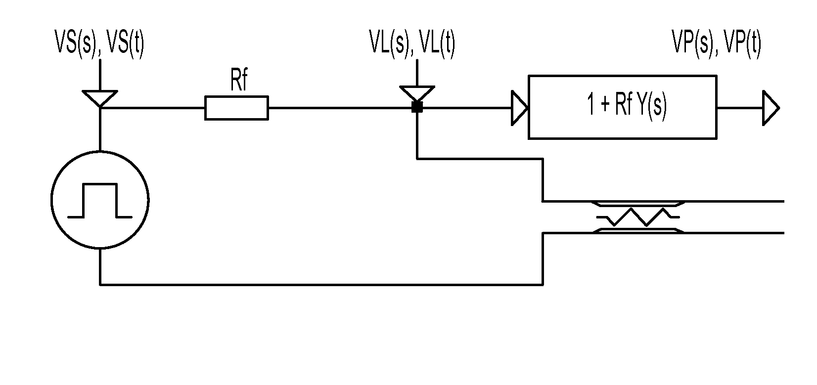
Standard Transmission Line TermsRis the distributed line resistance per unit lengthLis the distributed line inductance per unit lengthGis the distributed line conductance per unit lengthCis the distributed line capacitance per unit lengthY(s)is the line input admittance in Laplaceform = √((sC + G) / (sL + R))Z(s)is the line input impedance in Laplace form = 1 / Y(s)Y(t)is the time doma...


PUM


Abstract

The present invention provides a time domain reflectometer for testing an electrical cable. The time domain reflectometer includes a test signal generator, at least one line feed resistor, connected between the test signal generator and a pair of terminals, for connection to the ends of the electrical cable under test, and a signal processor, connected to the terminals, to receive a line signal including a reflection of a test signal transmitted into the cable under test. The signal processor is programmed to filter the line signal to enhance a portion of the signal indicative of any fault on the cable by balancing the signal according to the electrical characteristics of a normal cable of the same type as the cable under test by applying a filter function, and acquiring at least one estimate of the input admittance of the transmission line from known or estimated electrical characteristics of the cable under test.

Description

CROSS-REFERENCE TO RELATED APPLICATIONS[0001]This application claims priority to GB 0805407.4, filed on Mar. 25, 2008 and entitled “Time-Domain Reflectometer,” the disclosure of which is incorporated herein by reference in its entirety.FIELD OF THE INVENTION[0002]This invention relates to a time-domain reflectometer and to a method of time-domain reflectometry, for testing electrical cables that may be faulty or have faulty terminations.BACKGROUND OF THE INVENTION[0003]Whenever a signal travelling along a transmission line encounters some change, i.e., discontinuity, in the line characteristic, a portion of the signal is reflected back towards the sending end of the line. The nature of the reflection signal is determined by the discontinuity characteristic, which might be anywhere between a short circuit and an open circuit.[0004]Time domain reflectometers provide a means to determine the characteristics of faulty and normal electrical transmission lines, by sending an excitation si...

Claims


Application Information

Patent Timeline
Patent Type & Authority Patents(United States)
IPC IPC(8): G01R31/11
CPCG01R31/11G01R31/08
Inventor MASLEN, STEPHEN
Owner RADIODETECTION
Why Eureka
Try Eureka