
Integral composite rocket motor dome/nozzle structure

a composite, rocket motor technology, applied in the direction of vessel construction, marine propulsion, propulsive elements, etc., can solve the problems of multiple bond joints that may come apart, carbon-carbon insulation cannot be bonded directly to the steel shell,

Active Publication Date: 2011-07-19
RAYTHEON CO
View PDF11 Cites 16 Cited by
  • Summary
  • Abstract
  • Description
  • Claims
  • Application Information

AI Technical Summary

Benefits of technology

The present invention provides an integral composite rocket motor nozzle that includes a first layer of reinforcement material and a second layer of reinforcement material with a common matrix material. The reinforcement materials provide structural support and the matrix material provides thermal insulation. The nozzle may also include a third layer of reinforcement material for additional thermal insulation. The first layer is shaped to form an integrated dome and nozzle structure, and the common matrix material is a high temperature resin. The technical effect of this invention is to provide a more efficient and reliable rocket motor nozzle that can withstand high temperatures and provide better insulation.

Problems solved by technology

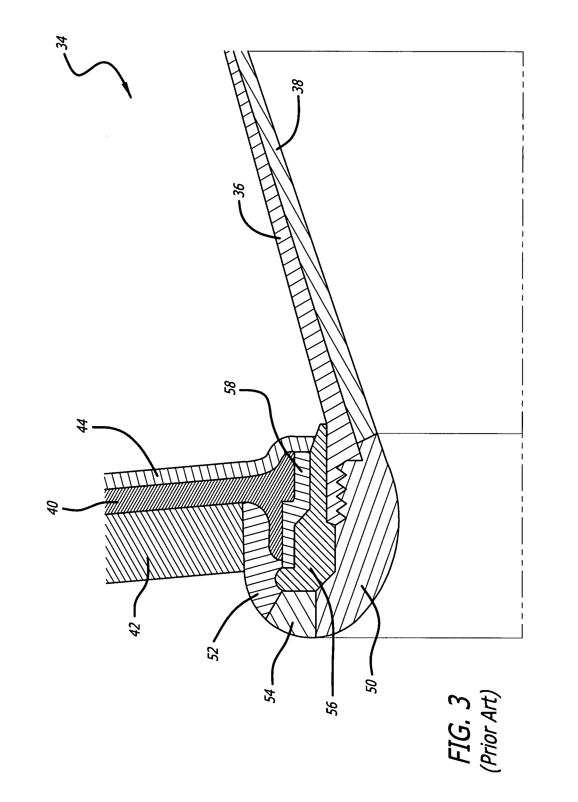
The carbon-carbon insulation therefore cannot be bonded directly to the steel shell, since the large TCE differential could cause the bond to break when heated.
These multiple insulation layers, however, result in multiple bond joints that may come apart when subject to extreme heat loads.
This can become a problem particularly for pulsed rocket motors.
After a propellant segment is burned through, the heat from the exhaust diffuses through the multiple layers of the dome / nozzle assembly, weakening the bond joints.
This can be very difficult to achieve with conventional dome / nozzle designs.
In addition, the multiple laminate interfaces with differing materials found in traditional rocket motor aft bodies require thick bond joints, o-rings, gaskets, and seals to achieve a thermal shock capability during propulsion ignition and burn, all involving significant manual labor, structural weight, assembly cost and complexity.

Method used


Image

  • Integral composite rocket motor dome/nozzle structure
  • Integral composite rocket motor dome/nozzle structure
  • Integral composite rocket motor dome/nozzle structure

Examples


Embodiment Construction

[0017]Illustrative embodiments and exemplary applications will now be described with reference to the accompanying drawings to disclose the advantageous teachings of the present invention.

[0018]While the present invention is described herein with reference to illustrative embodiments for particular applications, it should be understood that the invention is not limited thereto. Those having ordinary skill in the art and access to the teachings provided herein will recognize additional modifications, applications, and embodiments within the scope thereof and additional fields in which the present invention, would be of significant utility.

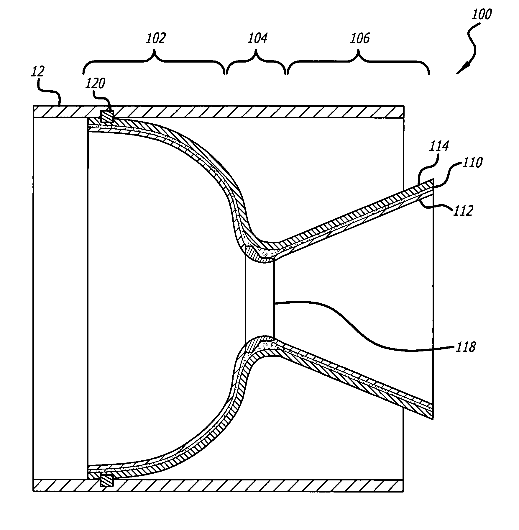
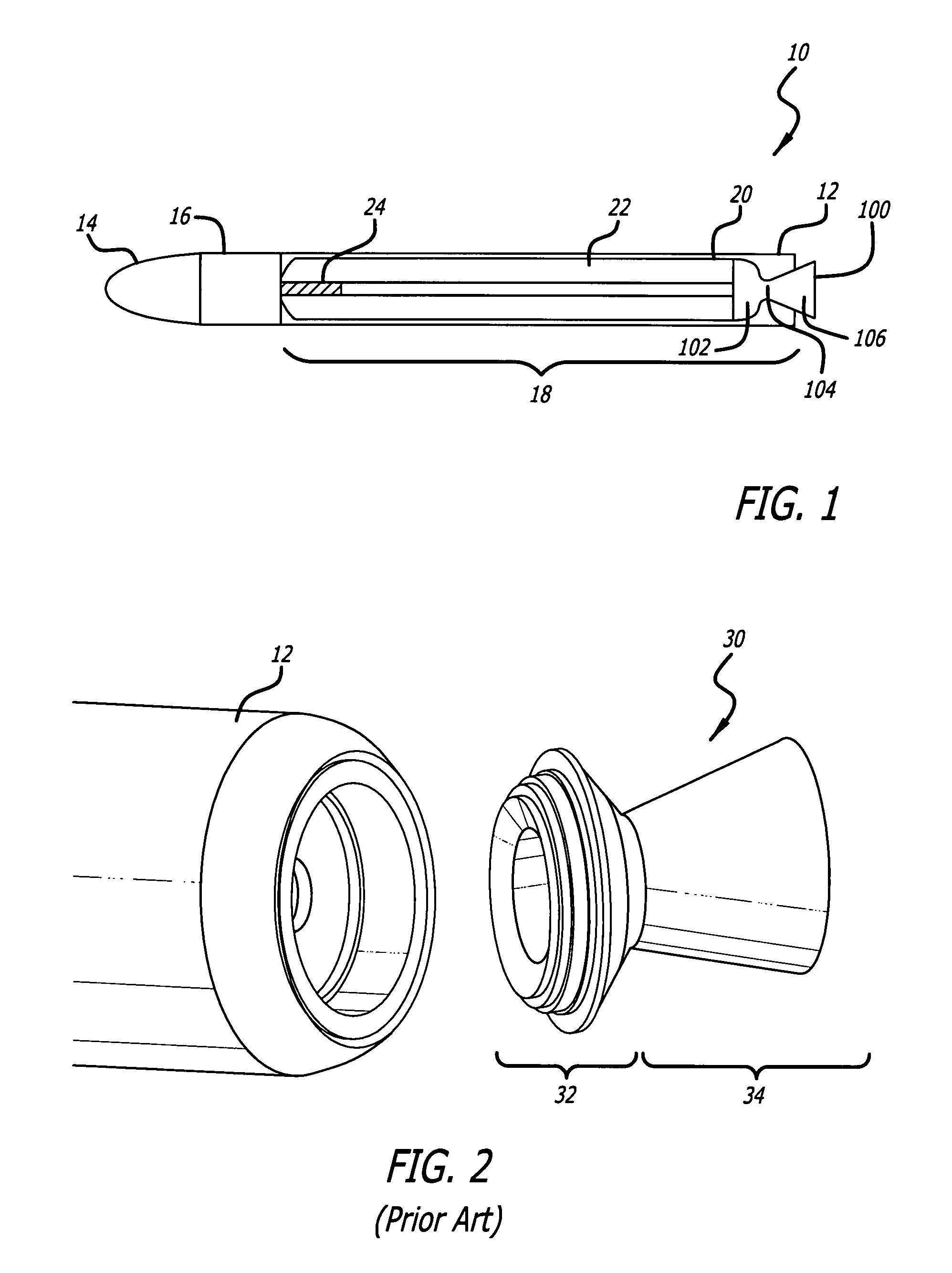
[0019]FIG. 1 is a simplified schematic of an illustrative missile 10 with a rocket motor nozzle 100 designed in accordance with an illustrative embodiment of the present invention. The illustrative missile 10 includes a missile body 12, which houses a sensor 14 for locating a target, a guidance system 16 for guiding the missile 10 toward the target,...


PUM

PropertyMeasurementUnit
temperaturesaaaaaaaaaa
thermal insulationaaaaaaaaaa
temperatureaaaaaaaaaa

Abstract

An integral composite rocket motor nozzle. The novel nozzle includes a first layer of a first reinforcement material, a second layer of a second reinforcement material, and a common matrix material surrounding the first and second reinforcement materials such that the reinforcement materials and matrix material form a single integral composite structure. In an illustrative embodiment, the first reinforcement material includes graphite fibers for providing structural support, and the second reinforcement material includes glass or quartz fibers for providing thermal insulation on a first side of the first layer. The nozzle may also include a third layer of a third reinforcement material for providing thermal insulation on a second side of the first layer. In a preferred embodiment, the first layer is shaped to form an integrated dome and nozzle structure.

Description

REFERENCE TO COPENDING APPLICATIONS[0001]This application claims the benefit of U.S. Provisional Application No. 60 / 931,091, filed May 21, 2007, the disclosure of which is hereby incorporated by reference.BACKGROUND OF THE INVENTION[0002]1. Field of the Invention[0003]The present invention relates to missiles and rocket motors. More specifically, the present invention relates to rocket motor nozzles.[0004]2. Description of the Related Art[0005]Rocket motors typically create thrust by expelling a high-temperature exhaust produced by the combustion of solid or liquid propellants through a nozzle. The hot gas (or liquid or plasma) exhaust exits from the combustion chamber through a narrow opening (or “throat”) into the nozzle. The nozzle is shaped such that it causes the gas to expand and accelerate, converting the thermal energy into kinetic energy. As the gas expands, it exerts pressure against the walls of the nozzle, forcing the missile in one direction while the gas accelerates in...

Claims


Application Information

Patent Timeline
Patent Type & Authority Patents(United States)
IPC IPC(8): F02G1/00F02K9/68F02G3/00
CPCB29C70/28F02K9/97B29K2079/08B29K2307/00B29K2309/08B29K2995/0015B29L2031/777F05D2300/2102F05D2300/44F05D2300/224F05D2300/434F05D2300/603F05D2300/614F05D2300/211
Inventor FACCIANO, ANDREW B.MOORE, ROBERT T.SINNOCK, KELLY J.CALDWELL, SCOTT T.
Owner RAYTHEON CO
Learn More