LED dazzler shield

a shield and shield technology, applied in the field of light source systems, can solve the problems of unsuitable crowd control situations with more than a few subjects, limited range of tasers, unsuitable for subduing more distant subjects, etc., to achieve enhanced crowd control, increased user safety and utility of invention, and increased illumination

Inactive Publication Date: 2011-07-19
GOLDFINCH
View PDF3 Cites 13 Cited by
  • Summary
  • Abstract
  • Description
  • Claims
  • Application Information

AI Technical Summary

Benefits of technology

[0014]The present invention is a shield fashioned to produce a “dazzling” effect: disorientation and temporary and fully reversible blindness in subjects for the purpose of threat deterrence, that further enhances the crowd control, user safety and utility of the invention in both civilian law enforcement and military engagements. The apparatus is comprised of a plurality of light emitting diodes (LEDs) capable of intense illumination. Light emitted by each LED is further pulsed and focused by reflective optics to produce a dazzling effect. Embodiments of the invention further provide ballistic protection, chemical or electrical crowd control functionality, safety-glass breaking capability, and optically propagated communications.

Problems solved by technology

While Tasers are routinely employed in domestic civilian law enforcement to subdue individual opponents, because the operation of a standard Taser projects a wired electrical connection between a voltage source (typically part of the Taser apparatus held by he user) and the dart propelled into the skin of the subject, it is not well suited to crowd control situations with more than a few subjects.
Further, Tasers have a limited range, nominally on the order of 32 feet, rendering them unsuitable for subduing more distant subjects.
Furthermore, while Tasers and related electro-shock weapons are not technically considered lethal, some governmental authorities as well as some non-governmental organizations question the safety of the use of Tasers.
Yet further some civilian organizations, such as Amnesty International, allege that the use of these weapons is inhumane and unethical and call for a moratorium on their use until further research establishes that they may be safely and humanely deployed.
There are serious safety concerns about the use of water cannon for riot control as well.
A modern water cannon can produce streams of water at extremely high water pressures (up to 435 pounds per square inch), which is capable of breaking subject's bones and causing significant injury to internal organs such as the spleen.
Further, in much of the free world the use of such weapons has negative associations with official oppression because of their extensive employment in suppressing unarmed civil rights protesters both in the United States and abroad.
Such wide dispersal agents cause irritation and pain to the subject's eyes, respiratory system and skin, inducing the subject to leave the area of dispersal.
Because the use of dispersed irritants causes pain in the subjects, it is regarded by some organizations as inhumane and unethical.
Further, some evidence exists that prolonged exposure to such chemical irritants may cause interstitial scaring in the respiratory system of subjects.
And yet further, the value of chemical irritants for crowd control is limited by weather conditions, a shift in wind or heavy precipitation significantly limiting the effectiveness of such agents.
It has long been observed that brief exposure to high intensity light can have the effect of momentarily blinding a viewer after the light source is removed, so much so that the viewer can become disoriented or “dazzled”.
Laser dazzlers such as Diehl's require substantial power supplies to provide the current and voltage needed to power the lasers, limiting the mobility of such devices.
The humanitarian organization, Human Rights Watch, has opposed the use of laser dazzlers generally, taking the position that even lower powered lasers have the potential to cause permanent injury and has recommended that the United States discontinue all ongoing research and development of tactical laser weapons because of their potential use as blinding antipersonnel weapons.
While field commanders in military action abroad have requested dazzler technology to add to their arsenal of non-lethal weaponry, in response to humanitarian concerns and controversy surrounding the safety of laser weaponry generally, the adoption of laser dazzler technology by both military forces and civilian police forces has been relatively low.

Method used


Image

  • LED dazzler shield
  • LED dazzler shield
  • LED dazzler shield

Examples


Embodiment Construction

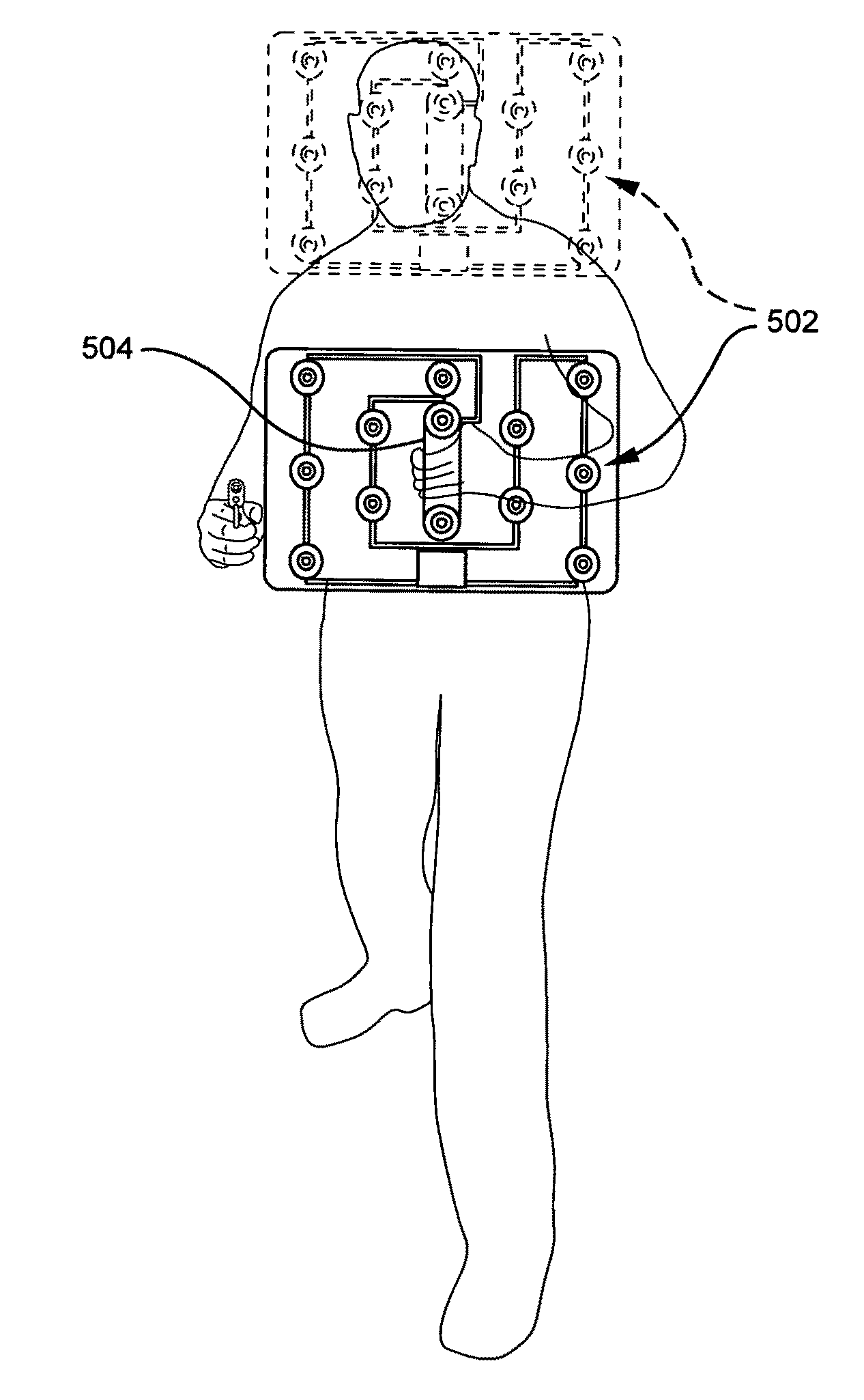
[0023]The present invention may be implemented in a number of form factors. Common to all embodiments, however, are an array of light emitting diodes driven by driver circuitry supplied with power from a power supply and operating in response to a signal source.

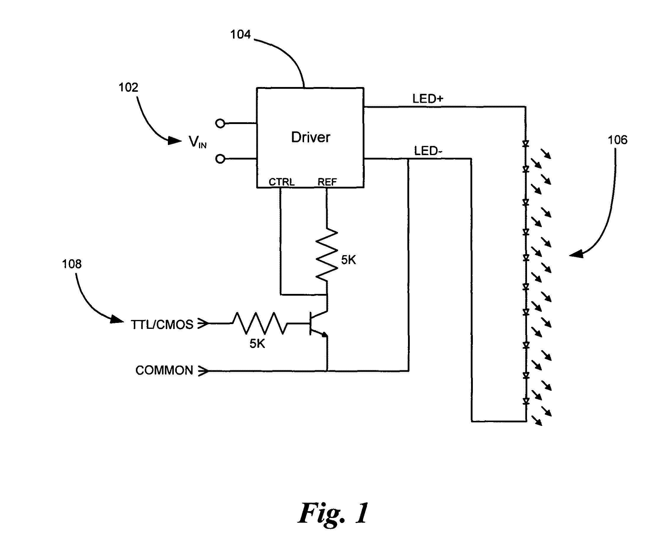
[0024]Turning to FIG. 1, illustrated is schematic electronic circuitry for a driver circuit powering an array of light emitting diodes. Power 102 is supplied to LED driver 104. In many applications, the dazzler device must be mobile and so typically the source of power 102 is a form of battery or fuel cell capable. It should be noted in any case that the amount of power necessary to drive an LED dazzler is considerably less than that for laser dazzlers and accordingly the power supplies for embodiments of the present invention may be much smaller and lighter than power supplies for laser based dazzlers.

[0025]In preferred embodiments, driver 104 should be pulse / strobe capable and should drive LEDs with constant current, result...


PUM


Abstract

A shield produces a “dazzling” effect: disorientation and temporary and fully reversible blindness in subjects for the purpose of threat deterrence. The apparatus is comprised of a plurality of light emitting diodes (LEDs) capable of intense illumination. Light emitted by each LED is further pulsed and focused by reflective optics to produce a dazzling effect. The shield further provides ballistic protection, chemical or electrical crowd control functionality, safety-glass breaking capability, optically propagated communications and an arm strap to further secure the shield.

Description

CROSS-REFERENCE TO RELATED APPLICATIONS[0001]This application is a continuation-in-part of U.S. patent application Ser. No. 12 / 152,539, titled “LED DAZZLER”, filed May 15, 2008.BACKGROUND OF THE INVENTION[0002]1. Field of the Invention[0003]This invention relates generally to systems of light sources and more particularly to non-lethal weapon systems comprised of light-emitting diodes for dazzling or stunning humans.[0004]2. Description of the Related Art[0005]In both civilian law enforcement and military action, it is often necessary for enforcers to render a hostile opponent harmless without causing death or permanent injury permanent injury to the subject. Such non-lethal threat deterrence employed at present includes high-voltage electrical weaponry sold under the trademark Taser®, high-pressure water jets or water cannons, and aerosol or gas dispersed chemical irritants such as CN and CS tear gases, pepper-spray, and the like. Each of the forgoing methods for non-lethal threat ...

Claims


Application Information

Patent Timeline
Patent Type & Authority Patents(United States)
IPC IPC(8): F21V33/00
CPCF41H5/08F41H13/00F41H13/0018F41H13/0087F21V33/0076F21Y2101/02F21Y2115/10
Inventor SHEMWELL, DAVID M.LONG, WEIHAO ALEXANDERCHALLENEGER, MICHAEL PERRYFUHRIMAN, JR., ROBERT LEELIMUTI, DONALD
Owner GOLDFINCH
Why Eureka
Try Eureka