
Method for controlling distribution of fluid components on a body

a fluid component and body technology, applied in the field of nanofabrication of structures, can solve the problem of uneven distribution of surfactants in the lamella layer, and achieve the effect of increasing the probability

Active Publication Date: 2011-07-19
MOLECULAR IMPRINTS
View PDF256 Cites 3 Cited by
  • Summary
  • Abstract
  • Description
  • Claims
  • Application Information

AI Technical Summary

Benefits of technology

[0006]An important characteristic with accurately forming the pattern in the polymerizable material is to reduce, if not prevent, adhesion to the mold of the polymeric material, while ensuring suitable adhesion to the substrate. This is referred to as preferential release and adhesion properties. In this manner, the pattern recorded in the polymeric material is not distorted during separation of the mold. Prior art attempts to improve the release characteristics employ a release layer on the surface of the mold. The release layer is typically hydrophobic and / or has low surface energy. The release layer adheres to the mold by covalent chemical bonding. Providing the release layer improves release characteristics. This is seen by minimization of distortions in the pattern recorded into the polymeric material that are attributable to mold separation. This type of release layer is referred to, for purposes of the present discussion, as an a priori release layer, i.e., a release layer that is solidified to the mold.

Problems solved by technology

An uneven distribution of surfactants in this material causes an uneven distribution of surfactants in the lamella layer.

Method used


Image

  • Method for controlling distribution of fluid components on a body
  • Method for controlling distribution of fluid components on a body
  • Method for controlling distribution of fluid components on a body

Examples


Embodiment Construction

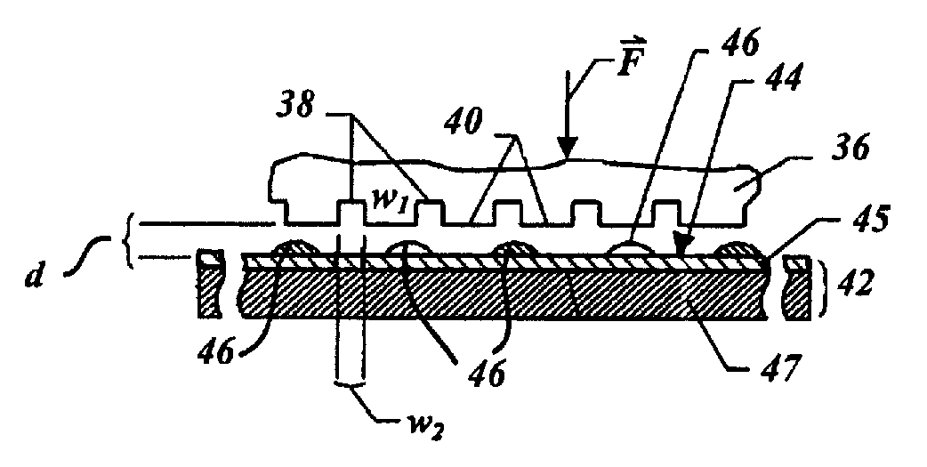
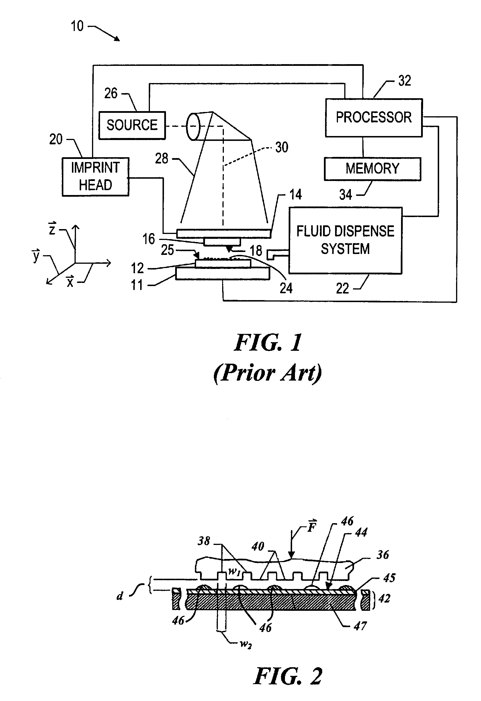
[0020]Referring to FIGS. 1 and 2, a mold 36, in accordance with the present invention, may be employed in system 10, and may define a surface having a substantially smooth or planar profile (not shown). Alternatively, mold 36 may include features defined by a plurality of spaced-apart recessions 38 and protrusions 40. The plurality of features defines an original pattern that forms the basis of a pattern to be formed on a substrate 42. Substrate 42 may comprise a bare wafer or a wafer with one or more layers disposed thereon, one of which is shown as primer layer 45. To that end, reduced is a distance “d” between mold 36 and substrate 42. In this manner, the features on mold 36 may be imprinted into a conformable region of substrate 42, such as an imprinting material disposed on a portion of surface 44 that presents a substantially planar profile. It should be understood that the imprinting material may be deposited using any known technique, e.g., spin-coating, dip coating and the ...


PUM

PropertyMeasurementUnit
lengthaaaaaaaaaa
viscosityaaaaaaaaaa
wavelengthaaaaaaaaaa

Abstract

The present invention provides a method of controlling the distribution of a fluid on a body that features compensating for varying distribution of constituent components of a composition that moved over a surface of a substrate. To that end, the method includes generating a sequence of patterns of liquid upon a substrate, each of which includes a plurality of spaced-apart liquid regions, with voids being defined between adjacent liquid regions. A second of the patterns of liquid of the sequence is arranged so that the liquid regions associated therewith are in superimposition with the voids of a first of the patterns of liquid of the sequence.

Description

CROSS REFERENCE TO RELATED APPLICATIONS[0001]The present application is a continuation-in-part of U.S. published patent application 2006-0062922-A1, filed as U.S. patent application Ser. No. 10 / 948,511 on Sep. 23, 2004 entitled “Polymerization Technique to Attenuate Oxygen Inhibition of Solidification of Liquids and Composition Therefor,” which is incorporated by reference herein.BACKGROUND OF THE INVENTION[0002]The field of invention relates generally to nano-fabrication of structures. More particularly, the present invention is directed to methods for controlling distribution of fluid components on a body in imprint lithographic processes.[0003]Nano-scale fabrication involves the fabrication of very small structures, e.g., having features on the order of one nanometer or more. A promising process for use in nano-scale fabrication is known as imprint lithography. Exemplary imprint lithography processes are described in detail in numerous publications, such as United States publishe...

Claims


Application Information

Patent Timeline
Patent Type & Authority Patents(United States)
IPC IPC(8): C08F2/48
CPCB82Y10/00G03F7/0002B82Y40/00A61P31/04B05D5/02
Inventor XU, FRANKMCMACKIN, IANLAD, PANKAJ B.WATTS, MICHAEL P. C.
Owner MOLECULAR IMPRINTS
Learn More