Circular accelerator

a technology of accelerators and beams, applied in accelerators, direct voltage accelerators, electric discharge tubes, etc., can solve the problems of long time expended, unstable beam outside the separatrix, and long time expended on the adjustment of emission parameters, so as to reduce the cost, shorten the beam adjustment time, and simplify the control

Inactive Publication Date: 2011-07-19
MITSUBISHI ELECTRIC CORP
View PDF8 Cites 43 Cited by
  • Summary
  • Abstract
  • Description
  • Claims
  • Application Information

AI Technical Summary

Benefits of technology

[0014]This invention has been made in order to solve the above problems, and it has for its object to provide a circular accelerator in which the change of a tune is statically corrected, and the tune is changed substantially linearly even when an equilibrium orbit has shifted, whereby a beam can be emitted stably with a simple control, and a beam adjustment time can be shortened, with the result that a cost is lowered.
[0016]Since such bending electromagnets are included, the time dependency of the magnetic field intensity of the six-pole electromagnet at a resonance emission conforms to a simple linear function. Accordingly, the adjustments of emission parameters at the time when the energy of charged particles accelerated during the emission has changed become easy, and an initial beam adjustment period, for example, at the construction of the circular accelerator, or after shutdown for a long term or after the partial remodeling of an apparatus can be sharply shortened. Thus, this invention has the advantage that the circular accelerator which enhances the reliability of running and which involves a low cost can be realized.

Problems solved by technology

The beam outside the separatrix becomes unstable, and it is gradually extracted out of the circular accelerator.
In this manner, the delicate adjustment of the tune is required in the resonance emission, and a long time is expended on the adjustments of emission parameters.
(1) The six-pole electromagnet or the like needs to be subjected to a complicated control in order to prevent the change of the tune attributed to the discrepancy of the equilibrium orbit as is ascribable to the change of the exciting current of the bending electromagnet or the other electromagnet, and a long time is expended on beam adjustments.
(2) Even in the emission of identical energy, in the case of the resonance emission, the charged particle beam passes on different beam orbits in the course of making the separatrix smaller. Therefore, a complicated control is required for preventing the change of the tune attributed to the change of the orbit, and a long beam adjustment time is expended.

Method used


Image

  • Circular accelerator
  • Circular accelerator
  • Circular accelerator

Examples


first embodiment

[0031]The first embodiment of this invention will be described in conjunction with the drawings.

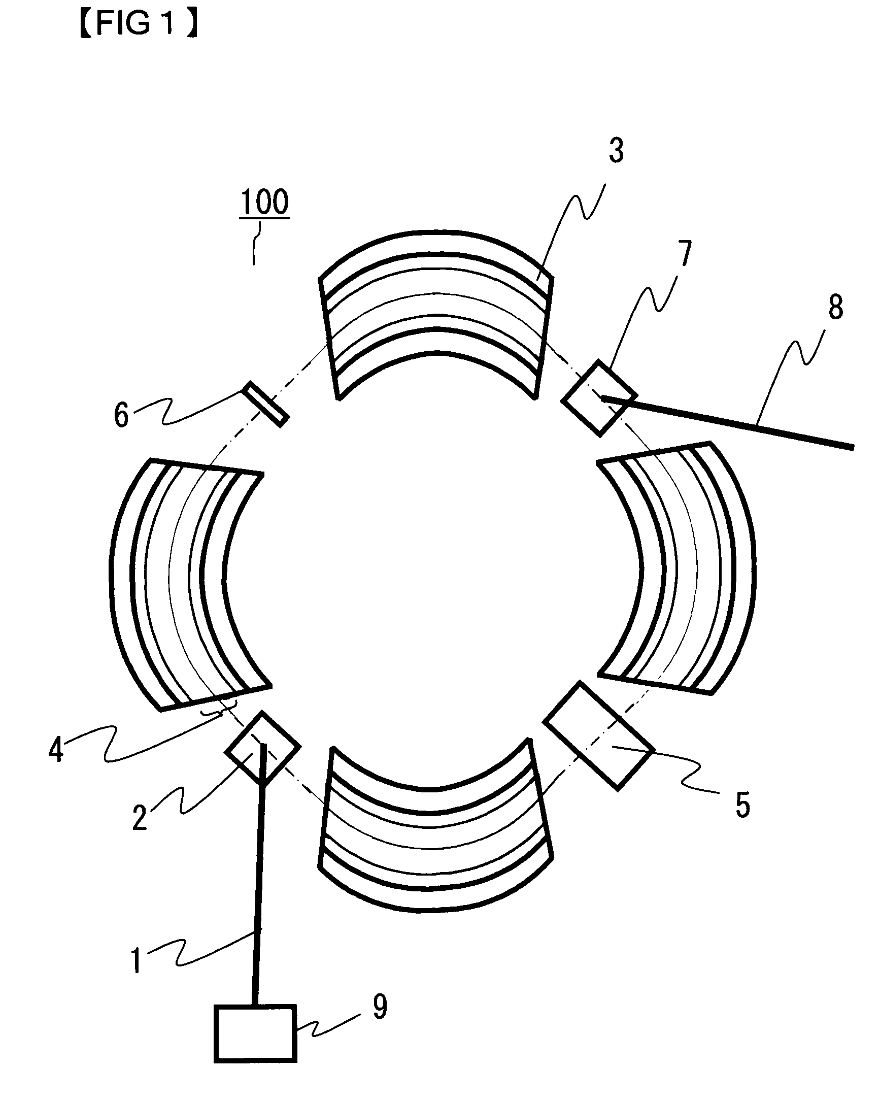
[0032]FIG. 1 is a view showing the equipment arrangement of a circular accelerator 100 according to the first embodiment. As is extensively known, the circular accelerator 100 is such that charged particles entered from a prestage accelerator 9 and through a beam transport system 1 are accelerated while being revolved around an equilibrium orbit 4 which is a revolving orbit, and that the charged particles are thereafter fed into an irradiation chamber, not shown, through an emission device 7 as well as an emitting beam transport system 8.

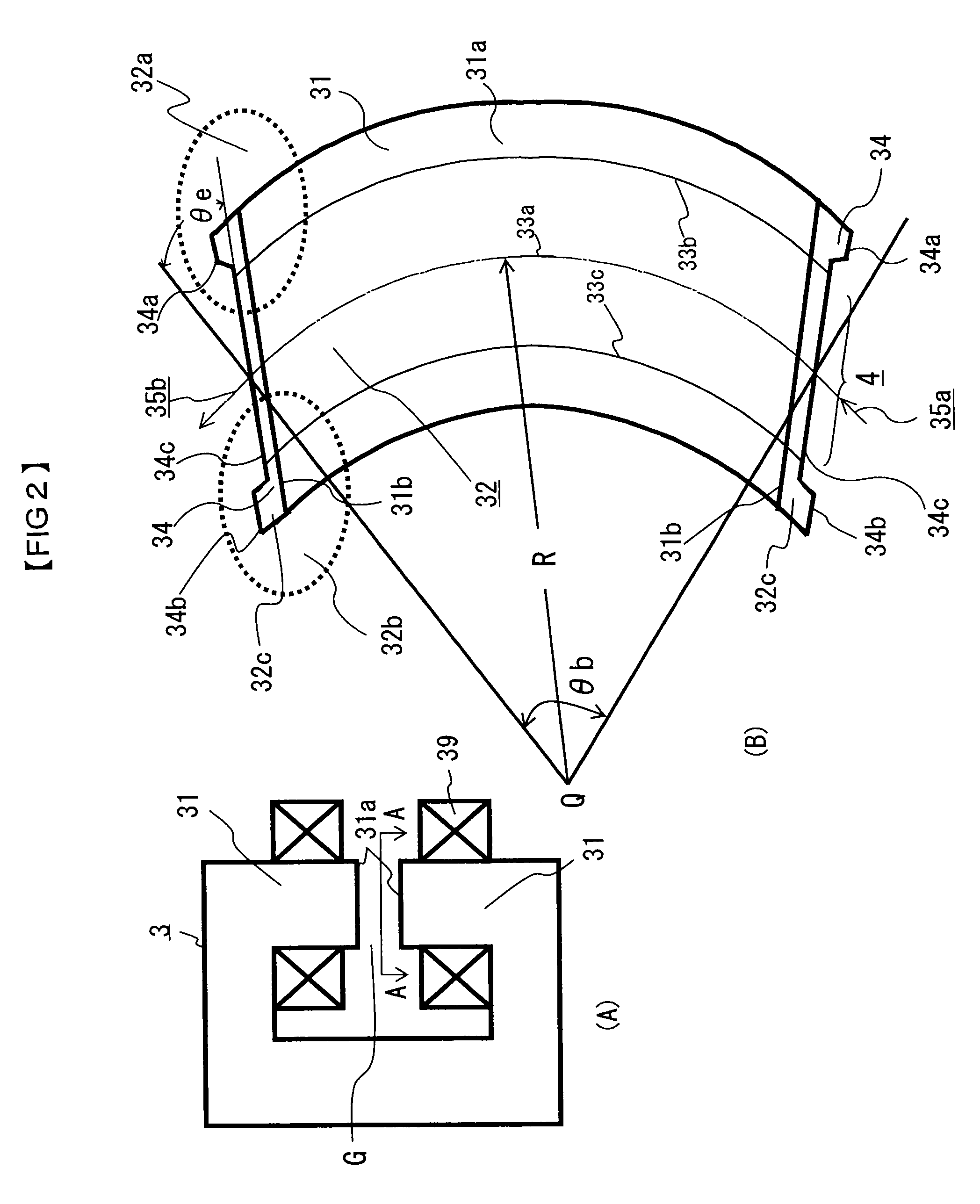
[0033]As shown in FIG. 1, the circular accelerator 100 includes an entrance device 2 which enters the beam of the charged particles, for example, protons transported from the prestage accelerator 9, a high-frequency acceleration cavity 5 which gives energy to the charged particles, bending electromagnets 3 which bend the beam orbit, a six-pole electromagn...

second embodiment

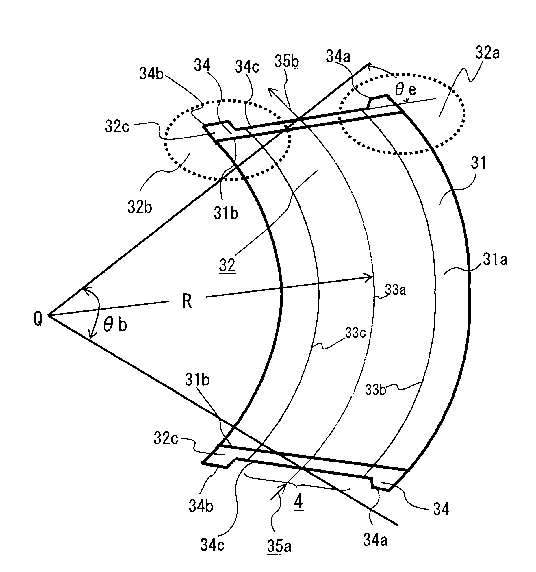
[0051]Next, a second embodiment will be described with reference to FIG. 10 which is a partial enlarged view of a magnetic pole edge portion 32.

[0052]As shown in FIG. 10, the length L1 of the first protrusion 34a of the endpack 34 and the length L2 of the second protrusion 34b are equalized, and the inclination angles are set to be θ2>θ1. That is, the flat parts 34d and 34e of the first and second protrusions 34a and 34b are identical, and the inclination angles θ1 and θ2 are not identical. Besides, the initial point S1 of the first equilibrium-orbit-side end part K1 of the first protrusion 34a is set to lie radially inside the equilibrium orbit 33b of a higher energy beam, and the initial point S2 of the second equilibrium-orbit-side end part K2 of the second protrusion 34b is set to lie radially outside the equilibrium orbit 33c of a lower energy beam.

[0053]The endpack 34 having such first and second protrusions 34a and 34b is additionally provided, whereby the energy dependency o...

third embodiment

[0054]A third embodiment will be described with reference to FIG. 11 which is a partial enlarged view of a magnetic pole edge portion 32.

[0055]As compared with FIG. 10 of the second embodiment, FIG. 11 differs only in the fact that the initial points of the first and second equilibrium-orbit-side end parts K1 and K2 of the first and second protrusions 34a and 34b of the endpack 34 are set at the intersection point S between these end parts and the equilibrium orbit 33a of a center energy beam. The others are the same as in FIG. 10.

[0056]Also in this case, the energy dependency of the tune can be made linear in the same manner as in the first embodiment. Accordingly, emission parameter adjustments at the change of energy are simplified, and an initial beam adjustment period can be sharply shortened.


PUM


Abstract

In a circular accelerator, a magnetic pole edge portion of a bending electromagnet into and from which a charged particle beam enters and exits is provided with endpacks. A first protrusion is provided at that part of each end pack which is radially outside the equilibrium orbit of a center energy beam, while a second protrusion is provided at that part of each end pack which is radially inside the equilibrium orbit of the center energy beam. The shapes of the first and second protrusions are set so that the betatron oscillation numbers of beams of different acceleration energies may be held constant or become linear to the energies. In case of emitting the charged particle beam out of the circular accelerator, the change of a tune attributed to the change of the beam orbit can be statically corrected, the tune is linearly changed, and an adjustment of the emission of the beam becomes easy.

Description

BACKGROUND OF THE INVENTION[0001]1. Field of the Invention[0002]This invention relates to a circular accelerator into which a low energy beam is entered, and from which a high energy beam accelerated on an equilibrium orbit is emitted.[0003]2. Description of the Background Art[0004]Heretofore, a circular accelerator such as a synchrotron has been used in a physical experiment in which a charged particle beam is revolved and accelerated, and a beam extracted from the equilibrium orbit of the circular accelerator is transported by a beam transport system, so as to irradiate a desired object with the extracted beam, or in the remedy of a cancer or the diagnosis of a diseased part for particle beam medicine.[0005]In such a circular accelerator, the resonance of the betatron oscillations of the beam has been employed in order to continuously emit accelerated charged particles. The “resonance of the betatron oscillations” is a phenomenon as stated below. The charged particles revolve whil...

Claims


Application Information

Patent Timeline
Patent Type & Authority Patents(United States)
IPC IPC(8): H05H11/00
CPCH05H7/04H05H3/00H05H5/00H05H11/00H05H13/00
Inventor TANAKA, HIROFUMIHIFUMI, TAKASHIYOSHIDA, KATSUHISAYAMAMOTO, KAZUOKURODA, YOICHI
Owner MITSUBISHI ELECTRIC CORP
Why Eureka
Try Eureka