Eureka AIR delivers breakthrough ideas for toughest innovation challenges, trusted by R&D personnel around the world.

Compact control device for a motor vehicle

Inactive Publication Date: 2011-07-19
CONTI TEMIC MICROELECTRONIC GMBH
View PDF24 Cites 7 Cited by
  • Summary
  • Abstract
  • Description
  • Claims
  • Application Information

AI Technical Summary

Benefits of technology

[0007]The object of the invention is to create a control device for a motor vehicle which enables an economic and mechanically reliable electrical connection between the control electronics of the control device and external electronic components in a compact design.
[0009]Conveniently, the foil conductors are designed as separate foil conductor strips. As a result, foil conductor material is saved, and when changes are made to the position of an electronic component outside of the frame which completely surrounds the interconnect device, the position of the corresponding foil conductor can be quickly adapted while retaining the position of the remaining foil conductors.
[0012]Preferably, the seal which runs around the entire frame and the seal which runs around an opening are produced from a single piece. As a result, in cases when the seal is designed as an insertion piece, the positioning of the sealing element is made easier due to the elimination of at least one operating stage. The respective sealing surfaces of the seals are separated by a groove in the area of openings, where they run almost parallel and adjacent to each other. As a result, the sealing areas of the openings are separated from the sealing area of the interconnect device as is the case with individual seals.
[0017]First, an interconnect device is directly attached to a base plate, e.g. by means of an adhesive. In this way, the base plate acts particularly effectively as a heat sink for the electronic components on the interconnect device. In particular, additional contact areas are also arranged on the interconnect device which are electrically connected via conductive paths to electronic components which are not arranged in the edge area of the interconnect device.

Problems solved by technology

The integration of the control device into the gearbox sets high demands on its thermal and mechanical stability.
With complex arrangements of the control device and the surrounding components, this leads to a large amount of waste of printed circuit board material and is therefore not economical, even if one only calculates or considers the recess for the electronic circuit in the center of the flexible printed circuit board.

Method used


Image

  • Compact control device for a motor vehicle
  • Compact control device for a motor vehicle
  • Compact control device for a motor vehicle

Examples


Embodiment Construction

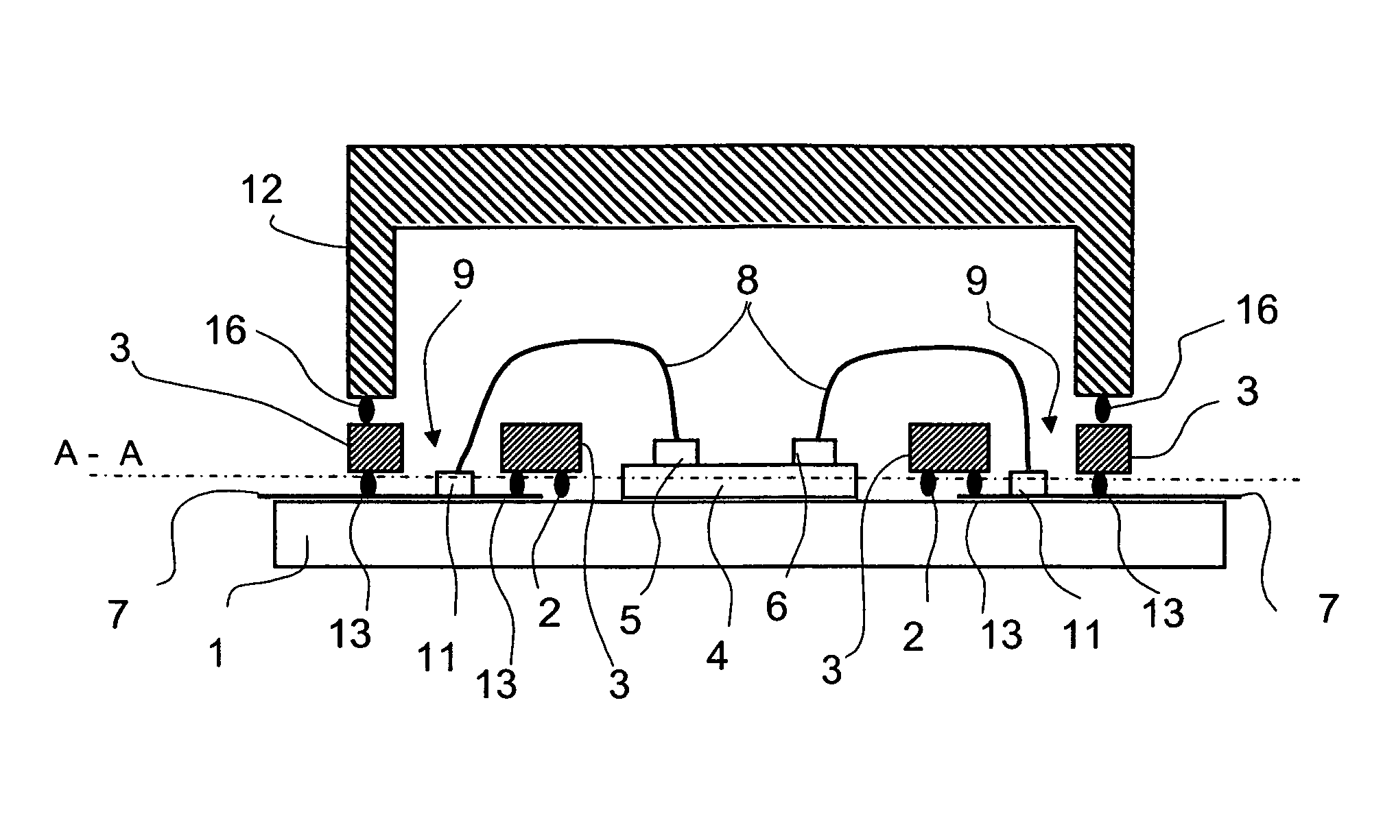
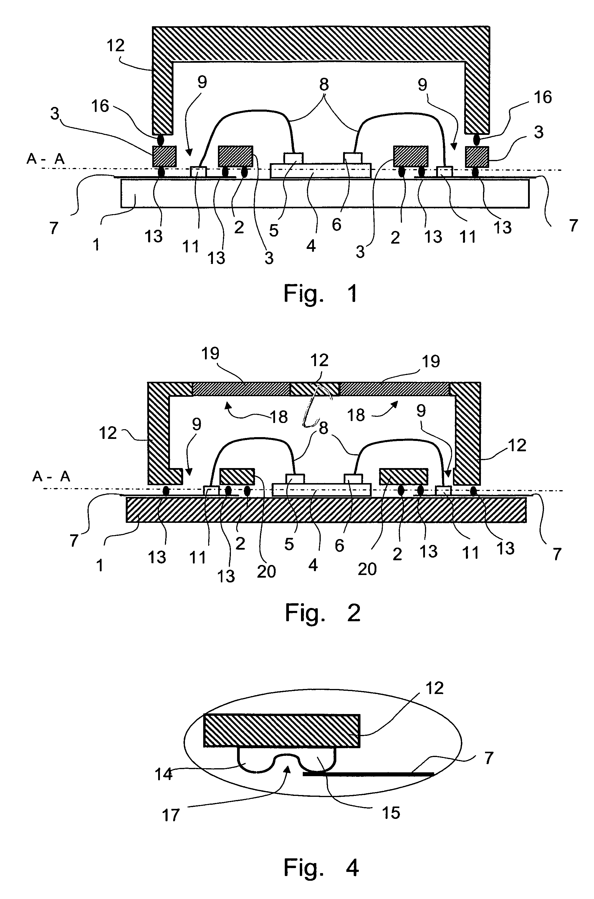
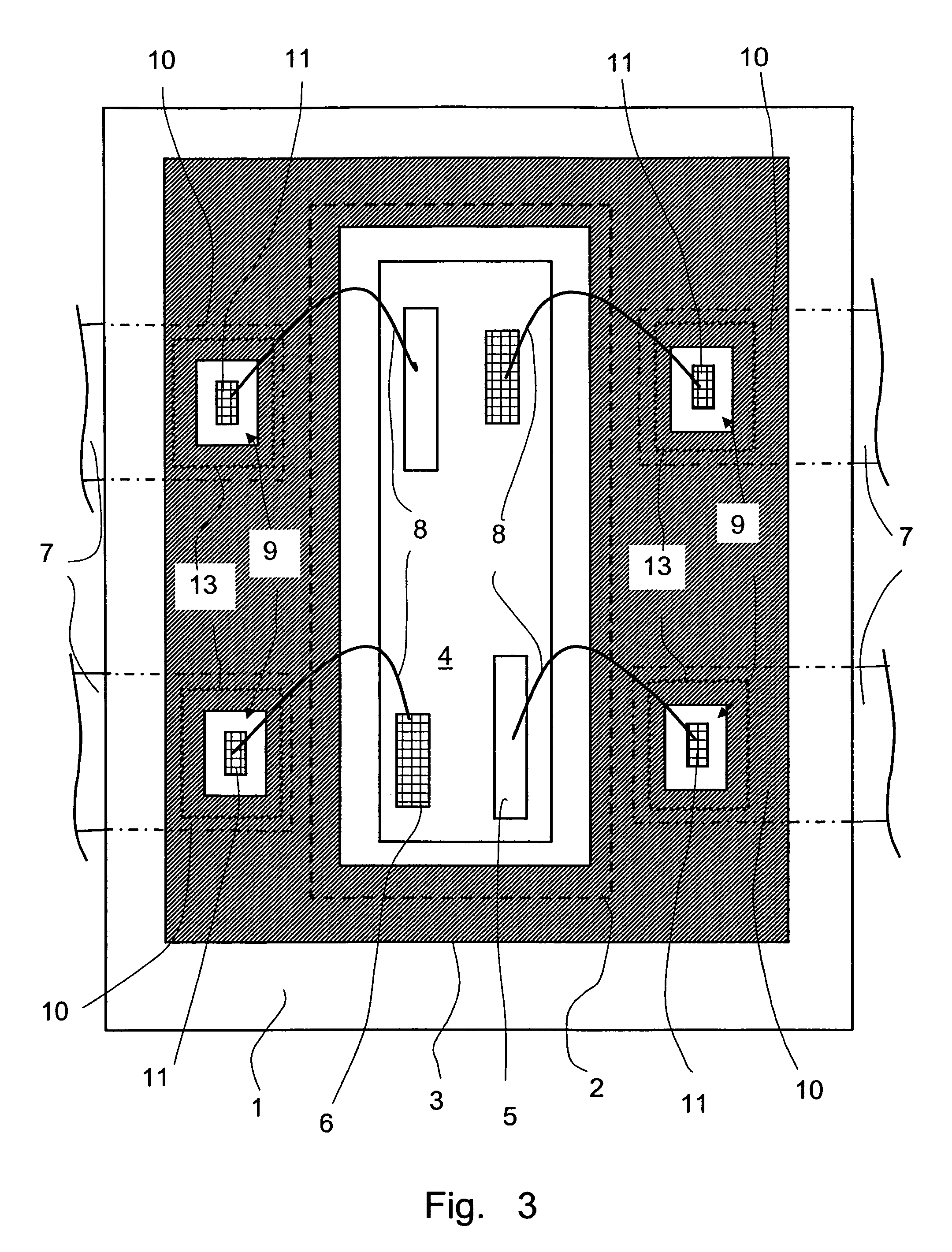
[0032]FIG. 1 shows a control device in which an interconnect device 4 is directly arranged on a base plate 1. The connection can be achieved by means of lamination, in particular cold lamination, or adhesion, preferably with an electrically insulating heat conducting adhesive. The base plate 1 is in particular made of metal and then acts simultaneously as a heat sink for the heat generated on the interconnect device 4. On the interconnect device 4, preferably in its edge area, at least one electronic component 5 of the control electronics is arranged. Components which are primarily arranged in the inner area of the interconnect device 4 are in particular electrically connected via conductive paths of the interconnect device 4, not shown here, with electrical contact areas 6 in the edge area of the interconnect device 4.

[0033]On the base plate 1, flexible foil conductor strips 7 are arranged around the interconnect device 4, leading away from the interconnect device 4. The electronic...


PUM

PropertyMeasurementUnit
Timeaaaaaaaaaa
Areaaaaaaaaaaa

Abstract

A motor vehicle control device includes a housing lid and a base plate that are connected with each other in an oil-tight manner via a frame. An interconnect device with at least one electronic component and / or at least one electrical contact area is arranged on the base plate. Respectively in the area of an electronic component and / or an electrical contact area, the base plate includes a foil conductor strip, of which an end section facing the interconnect device in turn includes an electrical contact area. The frame completely surrounds the interconnect device and includes one opening respectively in the area of an electrical contact area of the foil strip. Via connection lines, the electronics on the interconnect device are electrically connected with the contact area in the opening, and thus with the electronic components outside the control device.

Description

FIELD OF THE INVENTION[0001]The invention relates to a control device for a motor vehicle, wherein the control device includes an electronic or electrical element arranged in an oil-tight housing. The invention further relates to a method of manufacturing such a control device.BACKGROUND INFORMATION[0002]For some time, it has been a standard procedure in the motor vehicle manufacturing industry to integrate control devices for the engine or gearbox into the motor vehicle assembly to be controlled, i.e. the engine or gearbox. The gear control devices in particular form an extremely compact unit as an on-site control device. In comparison with the conventional use of external control devices, this arrangement has enormous advantages in terms of costs, weight, functionality and quality. In particular, this results in a significant reduction in plug-in connections and lines.[0003]The integration of the control device into the gearbox sets high demands on its thermal and mechanical stabi...

Claims


Application Information

Patent Timeline
IPC IPC(8): H05K5/00
CPCB60R16/0239H05K1/147H05K5/0082H05K5/069H05K1/142H05K3/0058Y10T29/5313H05K2203/049H05K2203/1147H05K2201/2018Y10T29/532H01L2224/48091H01L2924/00014
Inventor EGLINGER, MARKUSBUHL, JOACHIMGRAMANN, MATTHIASFUELLER, STEFFEN
Owner CONTI TEMIC MICROELECTRONIC GMBH
Why Eureka
Eureka Blog
Learn More