
Methods and apparatus for noise reduction in digital images

a digital image and noise reduction technology, applied in image enhancement, image analysis, instruments, etc., can solve the problems of affecting the quality of digital images, and introducing noise into images, so as to reduce the effect of color “ bleeding” and improve the quality of images

Active Publication Date: 2011-07-19
ADOBE INC
View PDF5 Cites 23 Cited by
  • Summary
  • Abstract
  • Description
  • Claims
  • Application Information

AI Technical Summary

Benefits of technology

[0005]Two color noise reduction methods are presented that may be used in embodiments. The first method, which may be referred to as higher-quality color noise reduction method, produces higher-quality results but is more expensive to compute. This first method applies a two-dimensional kernel as the noise reduction filter to both color channels. The two-dimensional kernel includes a weighting function that takes all three channels into consideration to minimize color “bleeding” at luminance and color boundaries in the image. The second method, which may be referred to as fast color noise reduction method, is much faster to compute, but may blur some fine color details. This second method first forms a 2-level image pyramid comprising a high-pass image and a lower-resolution, low-pass image. The two-dimensional kernel is applied to the color channels in the low-pass image. For the high-pass image, for each color channel, a rank filter is applied, followed by an adaptive threshold. The images are then combined to obtain noise-reduced image values for the color channels.
[0006]Two luminance noise reduction methods are presented that may be used in embodiments. The first method, which may be referred to as higher-quality luminance noise reduction method, produces higher-quality results but is more expensive to compute. The second method, which may be referred to as fast luminance noise reduction method, is much faster to compute, but may not produce quite as high quality results. Both of these methods identify detail pixels in the luminance channel and apply a one-dimensional filter to the detail pixels; a similar filter, but two-dimensional, is applied to the non-detail pixels. The detail pixels tend to represent edges; the one-dimensional filter is applied at each detail pixel in the direction perpendicular to the local image gradient at the pixel. Thus, the filtering for detail pixels is done along edges, not across edges, which helps to preserve edges and to reduce blurring across edges. In the first, method, the one- and two-dimensional filters are both applied to the full-resolution image. In the second method, a P-dimensional image pyramid is first formed that contains a lowest-resolution image as a low-pass image and one or more higher-resolution images. The two-dimensional filter is applied only to the low-pass image; the one-dimensional filter is applied to all of the higher-resolution images. The images are then combined to obtain noise-reduced image values for the luminance channel.
[0007]While these luminance channel filtering methods are described in relation to removing noise from the luminance channel of a three-channel luminance-chrominance image, these methods may also be applied to the single channel in one-channel (grayscale) images to remove or reduce noise in the images.

Problems solved by technology

Digital images, for example images captured with digital cameras or digitized from negatives, slides, or pictures, tend to include noise.
A camera sensor, lens, or other component may introduce noise into an image.
In addition, photon (shot) noise may be present even if the camera sensor itself is free of noise.
However, noise tends to be signal-dependent (e.g., brighter pixel values tend to have more noise than darker pixels).
This may pose difficulties for conventional noise filtering methods, as the methods may have to determine the brightness at each pixel to determine how much noise reduction to apply at the pixel.
Furthermore, many conventional noise filtering methods tend to either blur over edges, or in trying to preserve edges fail to smooth the image sufficiently in non-detail areas.
It can be shown that noise is signal-dependent (e.g., brighter pixel values tend to have more noise).
The first method, which may be referred to as higher-quality color noise reduction method, produces higher-quality results but is more expensive to compute.
The second method, which may be referred to as fast color noise reduction method, is much faster to compute, but may blur some fine color details.
The first method, which may be referred to as higher-quality luminance noise reduction method, produces higher-quality results but is more expensive to compute.
The second method, which may be referred to as fast luminance noise reduction method, is much faster to compute, but may not produce quite as high quality results.

Method used


Image

  • Methods and apparatus for noise reduction in digital images
  • Methods and apparatus for noise reduction in digital images
  • Methods and apparatus for noise reduction in digital images

Examples


example implementations

[0085]FIG. 7 illustrates an example noise reduction module that may implement one or more of the noise reduction techniques illustrated in FIGS. 1 through 6. Module 700 may, for example, implement one or more methods for reducing or removing noise from one-channel and / or N-channel (e.g., RGB) images. For example module 700 may implement the fast color noise reduction method, the fast luminance noise reduction method, the higher-quality color noise reduction method, and the higher-quality luminance noise reduction method. Alternatively, a module 700 may implement only the fast color noise reduction method and the fast luminance noise reduction method, or only the higher-quality color noise reduction method and the higher-quality luminance noise reduction method. Other combinations of the noise reduction methods may also be implemented in a module 700; for example, a module 700 may be implemented that only reduces noise in one-channel images, and therefore only implements the luminanc...

example camera

System

[0098]Embodiments of a noise reduction module and / or of the various image noise reduction methods as described herein may be implemented in various digital cameras. One such camera is illustrated by FIG. 9. In some embodiments of a camera 1100, the camera may include at least a main lens 1102 and a photosensor 1106 (e.g., a CCD or CMOS device). While main lens 1102 is shown as internal to the camera1100, in some cameras, such as DSLR cameras, main lens 1102 may be external and detachable so that the camera lens 1100 can be changed.

[0099]In general, embodiments of a camera 1100 may include, in addition to main lens 1102 and photosensor 1106, any other type of elements and features that may be found in digital cameras. For example, camera 1100 may include a shutter 1104 located in front of or behind main lens 1102, one or more processors 1118, and a power supply or power source 1116, such as one or more replaceable or rechargeable batteries. Camera 1100 may include a memory stor...


PUM


Abstract

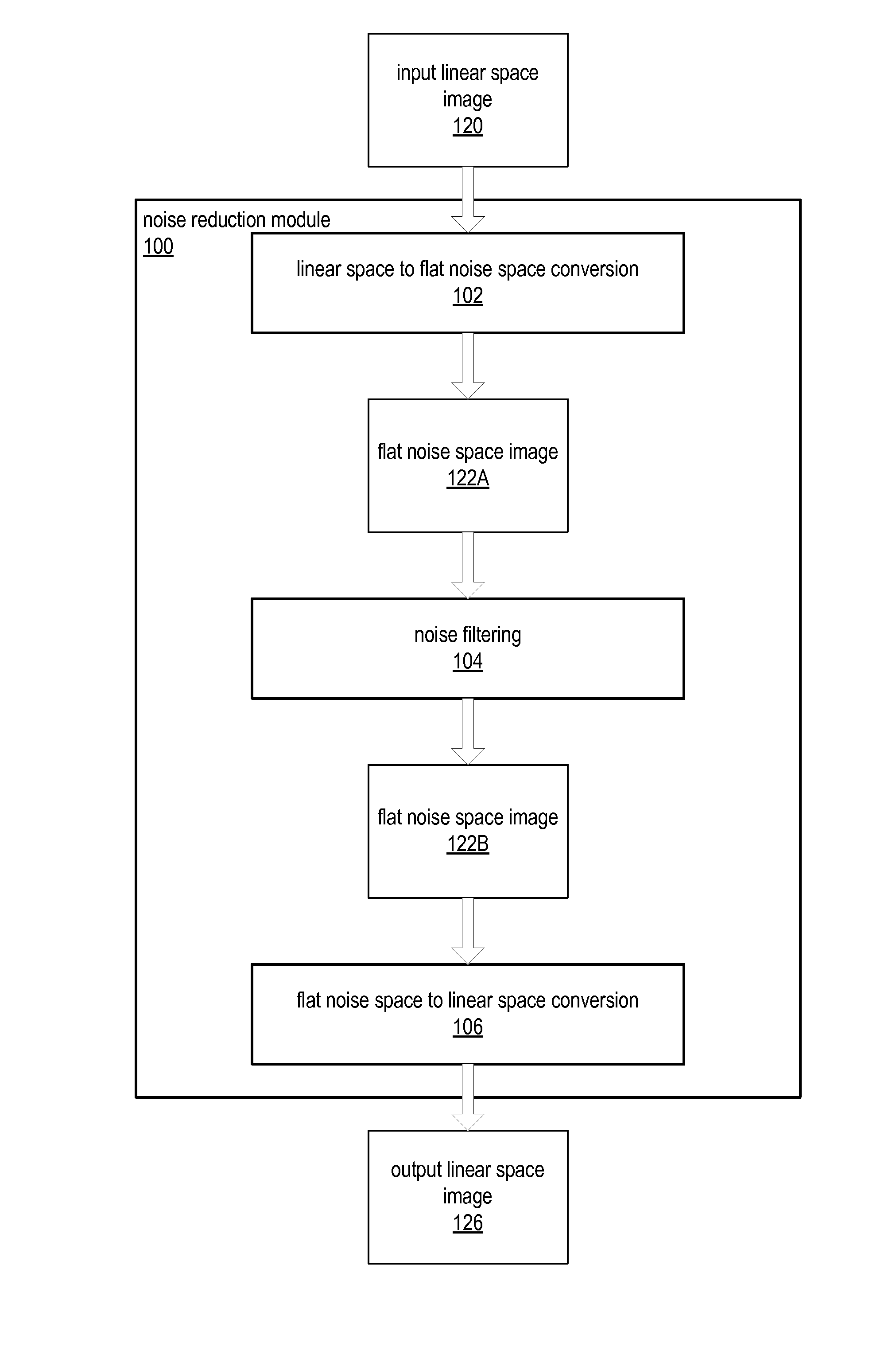
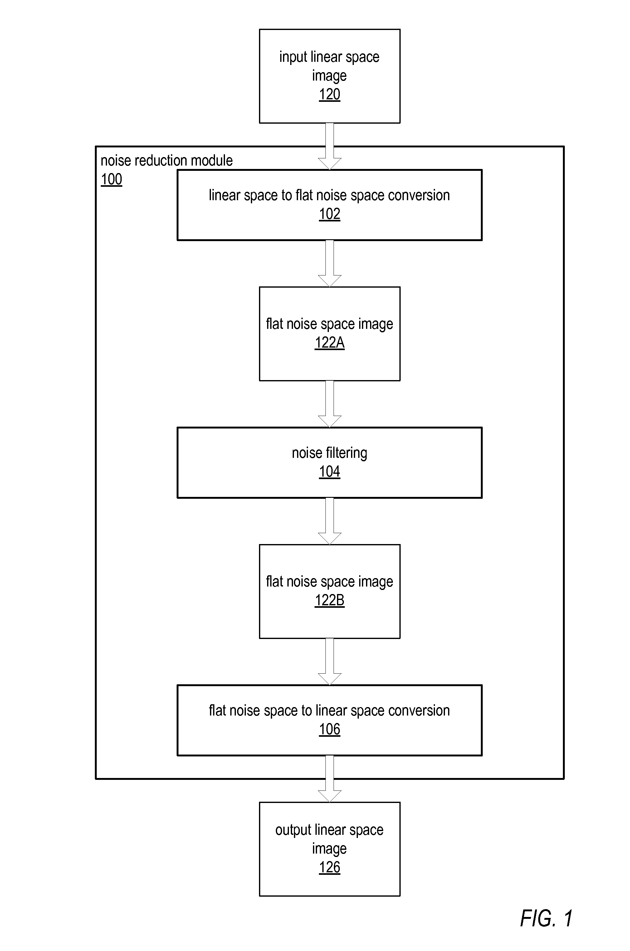
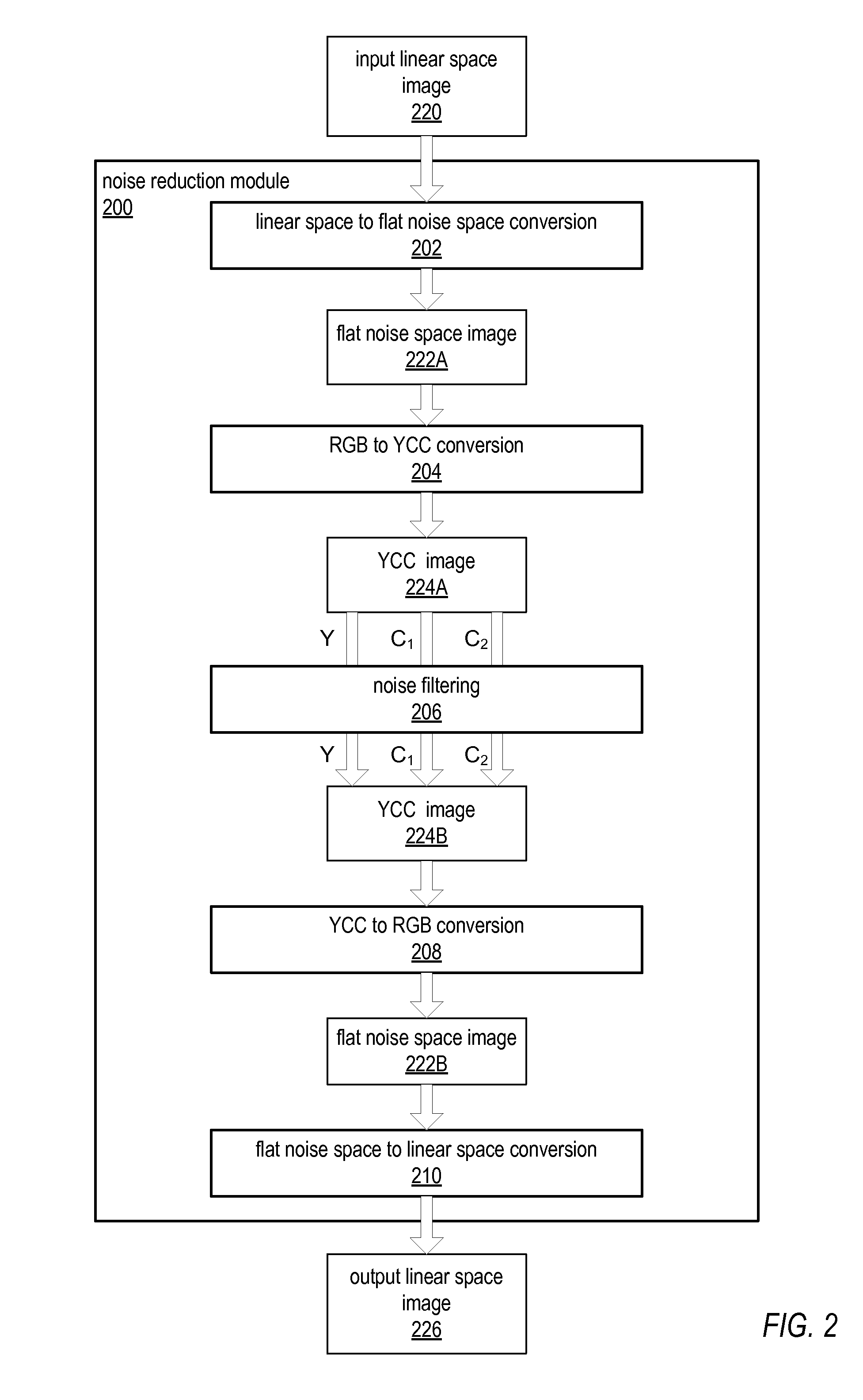
Methods and apparatus for reducing or removing noise in digital images. Image noise reduction methods are described that may be applied to grayscale and color images, for example RGB images. An image noise reduction method may, before applying a noise filtering technique, transform the image values from linear space to flat noise space in which the noise is independent of the signal. An edge-preserving noise filtering technique may then be applied to the image in flat noise space. After noise filtering is applied, the image is transformed from flat noise space back to linear space. For color images, the flat noise space may be converted from linear color space to luminance-chrominance space before applying the noise filtering technique so that different filters can be applied to luminance and color channels. After applying the noise filtering technique, the image is converted back to linear color space.

Description

BACKGROUNDDescription of the Related Art[0001]Digital images, for example images captured with digital cameras or digitized from negatives, slides, or pictures, tend to include noise. Noise may be introduced into a digital image by one or more sources. A camera sensor, lens, or other component may introduce noise into an image. In addition, photon (shot) noise may be present even if the camera sensor itself is free of noise. Noise may be expressed in a digital image as speckles, blotches, or other artifacts.[0002]Conventional noise filtering methods exist that may remove or reduce noise in digital images. However, noise tends to be signal-dependent (e.g., brighter pixel values tend to have more noise than darker pixels). This may pose difficulties for conventional noise filtering methods, as the methods may have to determine the brightness at each pixel to determine how much noise reduction to apply at the pixel. Furthermore, many conventional noise filtering methods tend to either ...

Claims


Application Information

Patent Timeline
IPC IPC(8): G06K9/40G06V10/30
CPCG06K9/40G06T5/002G06T2207/20192G06V10/30G06T5/70
Inventor CHAN, ERIC
Owner ADOBE INC
Learn More