Data transmitting apparatus

a data transmission and data technology, applied in the field of data transmission apparatus, can solve the problems of increasing the computational complexity of decryption, the inability to implement a method, and the number of attempts, so as to improve the security of eavesdropping and increase the multi-level number

Inactive Publication Date: 2011-07-26
PANASONIC CORP
View PDF14 Cites 25 Cited by
  • Summary
  • Abstract
  • Description
  • Claims
  • Application Information

AI Technical Summary

Benefits of technology

[0016]Therefore, an object of the present invention is to solve the above-described problems, and to provide a data transmitting apparatus which improves security against eavesdropping without extremely increasing a multi-level number.
[0026]Preferably, the accumulation section may set the value of the accumulated error signal lower than the predetermined criteria value when the recovery signal is inputted.
[0031]Further, the data transmitting apparatus can increase the number of the levels of the multi-level signal, which may be received by the eavesdropper, even in the case where a noise level overlapped on the multi-level signal is smaller than a step width of the multi-level signal. Accordingly, the data transmitting apparatus can improve the security against the eavesdropping without increasing the multi-level number included in the multi-level signal. Further, since the data transmitting apparatus is not required to increase the multi-level number included in the multi-level signal, it is possible to simplify an apparatus configuration.

Problems solved by technology

Accordingly, if the length of the key information is significantly long, the method is not practical.
In such a case, compared to a case without the erroneous decision (a stream cipher using a random number generator identical to that used for the first multi-level code generation section 911), the number of attempts, that is, computational complexity required for decryption is increased.
However, an increase in a value of the multi-level number M leads to complexity of a hardware configuration, and results in a problem of an increase in apparatus costs.

Method used


Image

  • Data transmitting apparatus
  • Data transmitting apparatus
  • Data transmitting apparatus

Examples


first embodiment

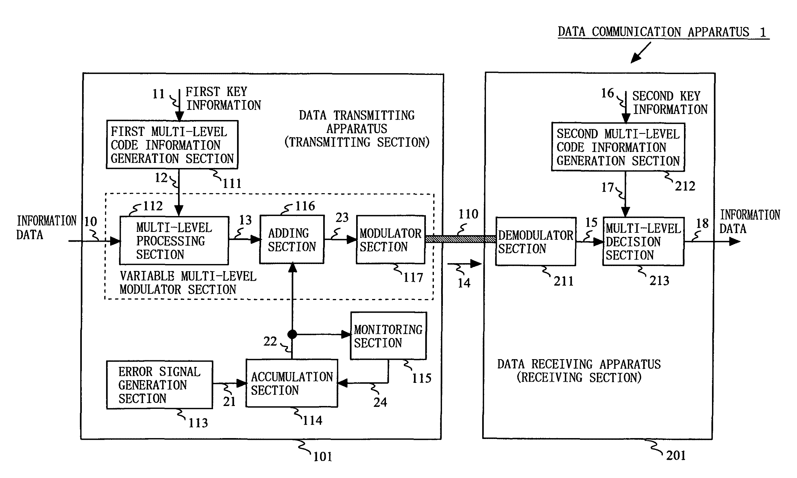
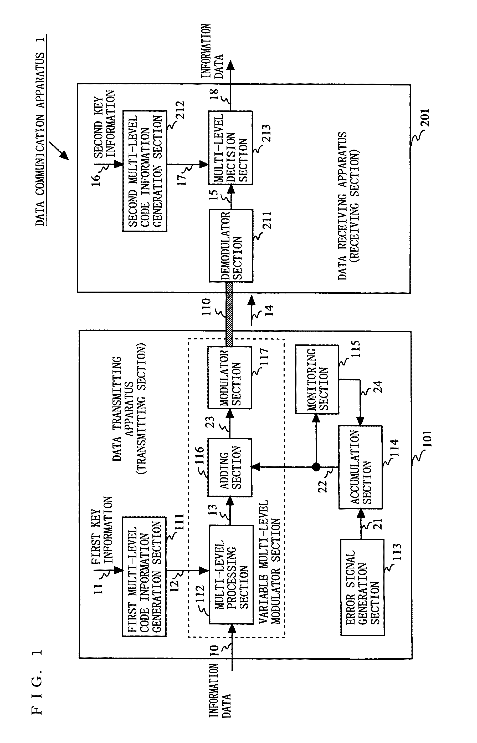
[0054]FIG. 1 is a block diagram showing an exemplary configuration of a data communication apparatus 1 according to a first embodiment of the present invention. As shown in FIG. 1, the data communication apparatus 1 has a configuration in which a data transmitting apparatus (hereinafter referred to as a transmitting section) 101 and a data receiving apparatus (hereinafter referred to as a receiving section) 201 are connected to each other via a transmission line 110. The transmitting section 101 includes a first multi-level code generation section 111, a multi-level processing section 112, an error signal generation section 113, an accumulation section 114, a monitoring section 115, an adding section 116, and a modulator section 117. The receiving section 201 includes a demodulator section 211, a second multi-level code generation section 212, and a decision section 213. As the transmission line 110, a metal line such as a LAN cable or a coaxial line, or an optical waveguide such as...

second embodiment

[0076]FIG. 10 is a block diagram showing an exemplary configuration of a data communication apparatus 2 according to a second embodiment of the present invention. As shown in FIG. 10, the data communication apparatus 2 has a configuration in which a transmitting section 102 and a receiving section 201 are connected to each other via a transmission line 110. The transmitting section 102 includes a first multi-level code generation section 111, a multi-level processing section 112, an error signal generation section 123, a accumulation section 114, a monitoring section 115, an adding section 116, and a modulator section 117. The receiving section 201 includes a demodulator section 211, a second multi-level code generation section 212, and a decision section 213. The data communication apparatus 2 according to the second embodiment is different in operation of the error signal generation section 123 from that of the first embodiment. The error signal generation section 123 generates an...

third embodiment

[0083]FIG. 14 is a block diagram showing an exemplary configuration of a data communication apparatus 3 according to a third embodiment of the present invention. As shown in FIG. 14, the data communication apparatus 3 has a configuration in which a transmitting section 103 and a receiving section 201 are connected to each other via a transmission line 110. The transmitting section 103 includes a first multi-level code generation section 111, a multi-level processing section 112, an error signal generation section 133, an accumulation section 114, a monitoring section 115, an adding section 116, and a modulator section 117. The receiving section 201 includes a demodulator section 211, a second multi-level code generation section 212, and a decision section 213. The data communication apparatus 3 according to the third embodiment is different in operation of the error signal generation section 133 from the first embodiment. The error signal generation section 133 generates an error si...


PUM


Abstract

A data transmitting apparatus has improved security against eavesdropping for secret communication using Y-00 protocol. The multi-level code generation section generates, based on key information, a multi-level code sequence in which a signal level changes so as to be approximately random numbers. The multi-level processing section generates a multi-level signal having a level which corresponds to a combination between information data and the multi-level code sequence. The error signal generation section generates an error signal which changes randomly. The accumulation section accumulates the error signal, and outputs an accumulated error signal. The adding section adds the accumulated error signal to the multi-level signal, and outputs a variable multi-level signal. The modulator section modulates the variable multi-level signal, and outputs a modulated signal.

Description

BACKGROUND OF THE INVENTION[0001]1. Field of the Invention[0002]The present invention relates to an apparatus for performing secret communication in order to avoid illegal eavesdropping and interception by a third party. More specifically, the present invention relates to a data transmitting apparatus for performing data communication through selecting and setting a specific encoding / decoding (modulation / demodulation) method between a legitimate transmitter and a legitimate receiver.[0003]2. Description of the Background Art[0004]Conventionally, in order to perform communication between specific parties, there has been adopted a structure for realizing secret communication by sharing original information (key information) for encoding / decoding between transmitting and receiving ends and by performing, based on the original information, an operation / inverse operation on information data (plain text) to be transmitted, in a mathematical manner.[0005]On the other hand, there have been ...

Claims


Application Information

Patent Timeline
Patent Type & Authority Patents(United States)
IPC IPC(8): H04L25/34
CPCH04L25/4917
Inventor IKUSHIMA, TSUYOSHIFURUSAWA, SATOSHISADA, TOMOKAZUFUSE, MASARUOHIRA, TOMOAKI
Owner PANASONIC CORP
Why Eureka
Try Eureka