Circuit of on-chip network having four-node ring switch structure

a switch structure and circuit technology, applied in the field of circuits of on-chip networks, can solve the problems of path collision, control complexity, and insufficient support of high bandwidth and high efficiency multi-component communications, and achieve the effects of maximizing local communication bandwidth, simple arbiter, and parallel data access

Inactive Publication Date: 2011-07-26
NATIONAL CHUNG CHENG UNIV +1
View PDF6 Cites 4 Cited by
  • Summary
  • Abstract
  • Description
  • Claims
  • Application Information

AI Technical Summary

Benefits of technology

[0004]The main purpose of the present invention is to provide multiple data transfer paths in parallel with a dynamic configuration between multiple processor cores or multiple functional units and registers for obtaining a low control complexity, an optimized local bandwidth, an optimized remote node path, a low routing complexity, and a simplified circuit.
[0006]The proposed four-node ring switch structure with bi-directional ring paths (one is clockwise, another is counterclockwise) supports efficient parallel data access while providing maximum local communication bandwidth. The proposed four-node ring switch structure contains a simple arbiter, high bandwidth, and easy replication and linking properties. The hierarchical construction four nodes ring structures provides a low-cost, flexible and large scalar design solution. Distributed arbiters are provided and the complexity is not increased greatly by ring nodes. Overall, the subject application provides efficient parallel data access, and a low-cost and flexible solution in multi-components communications.

Problems solved by technology

Yet, a traditional single channel bus is not enough for supporting high bandwidth and high efficiency multi-components communications.
However, path collision, control complexity, area overhead and power consumption are not easily optimized.
With respect to ring-based interconnect design, increasing the ring node number will heighten design complexity and complicate arbitration, buffer usage, path optimization.
Especially in arbitration, the complexity of the arbiter will increase exponentially by increasing the number of ring nodes.
More ring nodes sharing one ring path will limit bandwidth and increase traffic.
However, multiple ring nodes sharing multiple ring paths is not an easy design to implement.

Method used


Image

  • Circuit of on-chip network having four-node ring switch structure
  • Circuit of on-chip network having four-node ring switch structure
  • Circuit of on-chip network having four-node ring switch structure

Examples


Embodiment Construction

[0017]The following description of the preferred embodiment is provided to understand the features and the structures of the present invention.

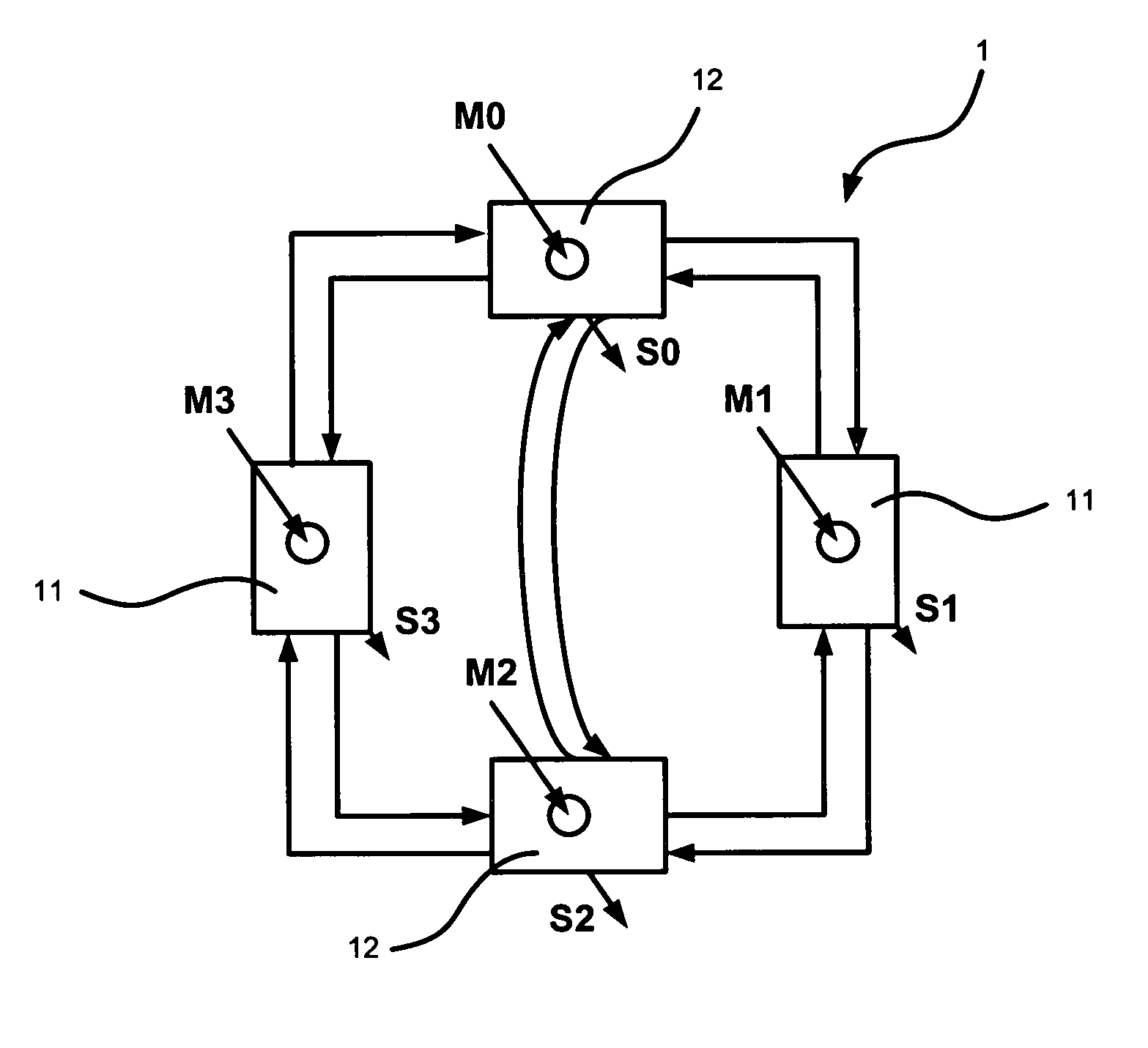
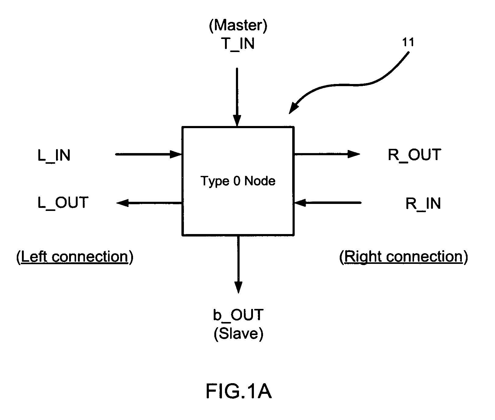
[0018]Please refer to FIG. 1A, FIG. 1B, FIG. 2A and FIG. 2B, which are views showing a type-0 ring node and a type-1 ring node for dual-directional data transfer according to a preferred embodiment of the present invention. As shown in the figures, the present invention is a circuit of an on-chip network having a four-node ring switch structure comprising two type-0 ring nodes 11 and two type-1 ring nodes 12 for dual-directional data transfer.

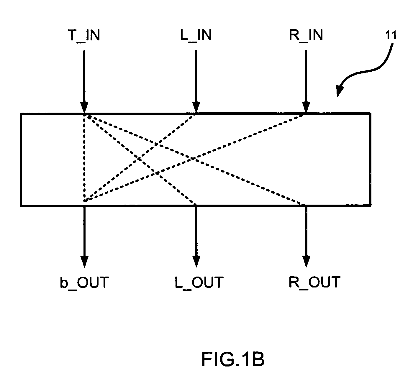
[0019]The type-0 ring node 11, as shown in FIG. 1A, comprises three data input ports and three data output ports for transferring and switching data and five data transferring lines (as shown in FIG. 1B), where two pairs of the data input ports and the data output ports are left side connection and right side connection data transfers respectively and the other pair of the data input port and the data ou...


PUM


Abstract

A hierarchical ring architecture is constructed with on-chip networks. The on-chip network includes two type-0 ring nodes and two type-1 ring nodes. Multiple data transfer is provided in parallel between multiple processor cores or multiple functional units and register banks with a dynamic configuration. A low control complexity, an optimized local bandwidth, an optimized remote node path, a low routing complexity, and a simplified circuit is thus obtained.

Description

FIELD OF THE INVENTION[0001]The present invention relates to an on-chip network; more particularly, relates to providing an optimized system-on-chip (SOC) design integrating multiple processor cores and IPs.DESCRIPTION OF THE RELATED ART(S)[0002]Communications between components of a multi-core processor or of a single core processor with multiple functional units are important. Yet, a traditional single channel bus is not enough for supporting high bandwidth and high efficiency multi-components communications. Thus, some other type of bus, like a crossbar bus, a multi-layer bus or a multi-node ring bus, enhances bandwidth and efficiency. However, path collision, control complexity, area overhead and power consumption are not easily optimized. In this application, Applicants target on improving ring-based on-chip networks. With respect to ring-based interconnect design, increasing the ring node number will heighten design complexity and complicate arbitration, buffer usage, path opt...

Claims


Application Information

Patent Timeline
Patent Type & Authority Patents(United States)
IPC IPC(8): G06F13/00H04L12/28G08C15/00H04J1/14
CPCG06F13/4022G06F15/17375G06F15/7825
Inventor CHOU, SHU-HSUANCHANG, MING-KUCHAN, YI-CHAOCHEN, TIEN-FU
Owner NATIONAL CHUNG CHENG UNIV
Why Eureka
Try Eureka