Method and apparatus for extending flow range of a downhole turbine

a turbine and flow range technology, applied in the direction of machines/engines, stators, liquid fuel engines, etc., can solve the problems of not providing techniques capable of extending the flow range, and achieve the effect of increasing fluid flow, extending the flow range, and increasing the fluid flow

Active Publication Date: 2011-08-02
SCHLUMBERGER TECH CORP
View PDF12 Cites 2 Cited by
  • Summary
  • Abstract
  • Description
  • Claims
  • Application Information

AI Technical Summary

Benefits of technology

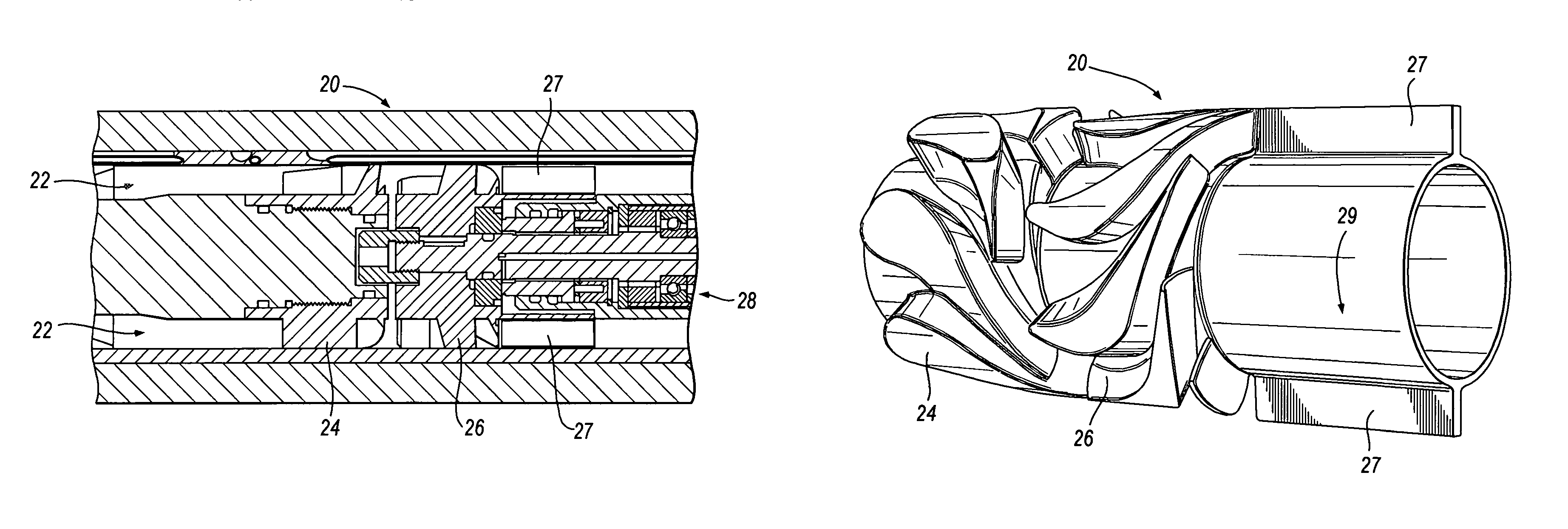
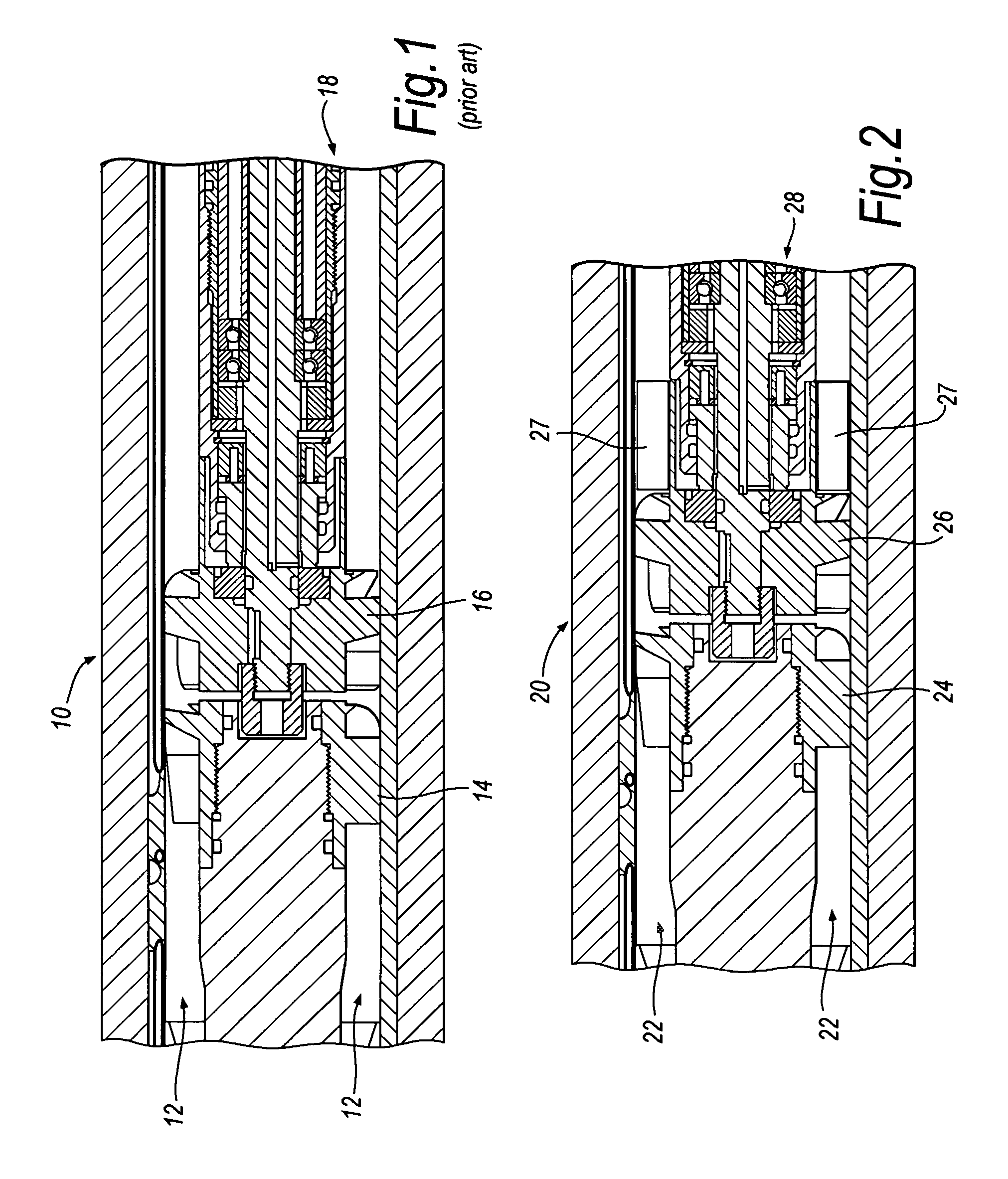
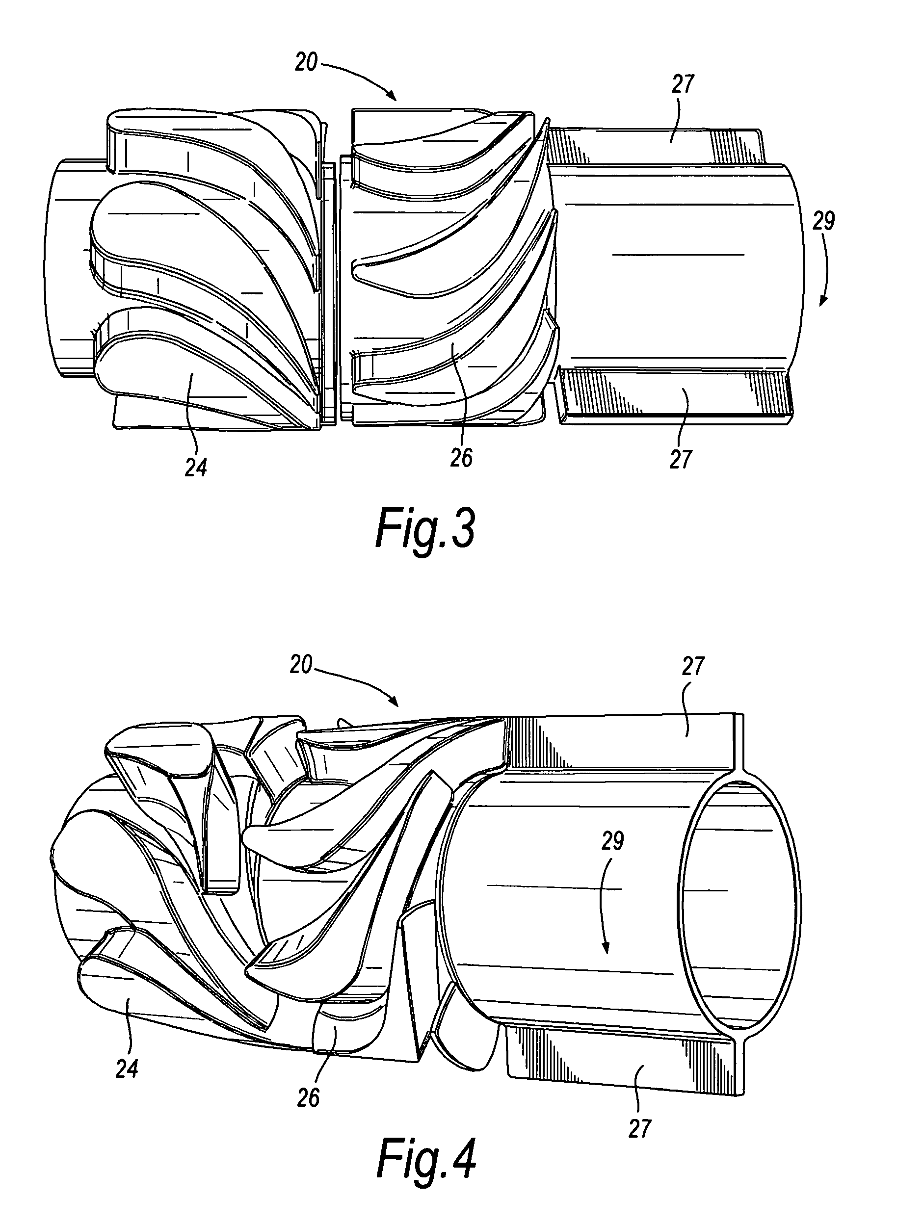
[0004]The present invention provides means to extend the flow rate range over which a turbine will return a power output sufficient to meet the minimum downhole power requirements. In one aspect, the present invention relates to an arrangement of axial vanes that are situated such that the rotation of the turbine generates an increasing drag force. This force acts on the turbine to reduce the rate of increase in speed such that the actual rotations per minute (rpm) is lower than what it would have been if the axial vanes were not present. This in effect, increases the flow range.
[0010]The present invention provides a method of extending the flow range of a downhole turbine comprising a stator having a fluid flow path imparting tangential and axial vector flow components on a fluid flowing past the stator; a rotor hydraulically communicating with the stator and impelled by the vectored fluid flow, and a shaft coupled to the rotor. The flow range can be extended by installing one or more braking vanes on the rotor to impart a drag force on the rotor as the rotor and braking vanes rotate, and increasing the fluid flow rate to activate the movement of the turbine.

Problems solved by technology

In this case, the overall mass flow focuses control on the apparatus and fails to disclose the use of an incompressible flow, velocity approach.
However, so far as known to applicants, these devices fail to provide techniques capable of extending flow ranges.

Method used


Image

  • Method and apparatus for extending flow range of a downhole turbine
  • Method and apparatus for extending flow range of a downhole turbine
  • Method and apparatus for extending flow range of a downhole turbine

Examples


example 1

[0064]The extension of the flow rate range resulting from use of a braking fin is depicted graphically in FIGS. 15a-15b and 16a-16b. Using a turbine and overall electrical and mechanical system parameters in a typical system to drill and measure 8.5 inch well bores, the overall estimated power and operating points can be modeled for systems with and without braking fins. FIGS. 15a and 16a illustrate the computation results for a system without braking fins at 300 gpm and 720 gpm water flow, respectively. FIGS. 15b and 16b illustrate the computation results for a system with braking fins at similar flow rates such that a direct comparison can be made. Each graph shows two power calculation results—the curved dashed line represents the net power resulting from the shaft rotation, and the solid curved line represents the power that can be generated from an electrical, mechanical, or hydraulic device operated by the rotor rotation, used to convert shaft rotation power to usable work (a ...

example 2

[0067]The extension of the flow rate range resulting from use of gates or extension elements is depicted graphically in FIGS. 17a-17c, where the lines represent data as previously described for FIGS. 15a-15b and 16a-16b. Again, using a turbine and overall electrical and mechanical system parameters in a typical system used to drill and measure 8.5 inch well bores, the overall estimated power and operating points can be modeled for systems with and without gates. FIG. 17a shows the model results for a system without restriction elements, where the stator area is not restricted, i.e. 100% open, and at a water flow rate of 200 gpm. Without restriction elements, the power generated from the turbine is below the threshold power required to operate the tool. At the same 200 gpm water flow rate, restricting flow through the stator, where the stator area is 50% open, results in power generation that allows the tools to operate, as shown in FIG. 17b. At a flow rate of 680 gpm water, the rest...


PUM


Abstract

The present invention provides means to extend the flow rate range over which a downhole turbine 70 will return a power output sufficient to meet the minimum downhole power requirements. In one embodiment, the present invention relates to an arrangement of axial vanes 77 that are situated such that the rotation of the rotor 76 generates an increasing drag force, thereby extending the upper limit of the flow rate range. In another embodiment, the present invention relates to an arrangement of restriction assemblies 75 that can be used to maximize the fluid velocity relative to the fluid flow rate past the stator 74 to achieve the necessary speed and power to rotate rotor 76, thereby extending the lower limit of the flow rate range. In another embodiment, the axial vanes 77 and restriction assemblies 75 are used in combination to further extend both the upper and lower limits of the flow rate range of the downhole turbine 70.

Description

BACKGROUND[0001]In many downhole drilling and measurement systems, a downhole power source is required. The power source can include direct power output from the torque and rotation of the drill string, electrical storage batteries, and turbines, among others. In a drilling environment where mud flow is present, there is an opportunity to use part of this hydraulic power to drive a turbine. The turbine can, in turn, rotate a variety of electrical, mechanical, or other devices to convert the hydraulic energy into a desired power output.[0002]Turbines, although efficient, must be operated within a narrow rotational speed range for optimum power output. The rotational speed of the turbine is related to the flow rate or velocity of the drilling mud. It is desirable to extend or maximize the range of flow rates (minimum to maximum) over which optimum power output can be achieved, such that the downhole operation can be used with the broadest possible hydraulic parameters desired in the d...

Claims


Application Information

Patent Timeline
Patent Type & Authority Patents(United States)
IPC IPC(8): F03B13/02F01D17/00
CPCE21B4/02F03B13/02Y10S415/903
Inventor MORIARTY, KEITH A.
Owner SCHLUMBERGER TECH CORP
Why Eureka
Try Eureka