Fluid-responsive oscillation power generation method and apparatus

a technology of power generation and fluid-responsive oscillation, which is applied in the direction of liquid fuel engine components, wind energy generation, rotary clutches, etc., can solve the problems of large amount of real estate and capital, large disruption of local environment, and large displacement of whole populations of people, so as to achieve less materials, expand the locale where, and the effect of lifting for

Inactive Publication Date: 2011-08-02
BIRKESTRAND ORVILLE J
View PDF73 Cites 28 Cited by
  • Summary
  • Abstract
  • Description
  • Claims
  • Application Information

AI Technical Summary

Benefits of technology

Accordingly it is the object of this invention to provide a smooth constant angular velocity output from an oscillating power generation apparatus which efficiently and safely extracts energy from a moving fluid to perform useful work.
As we shall see, my basic apparatus and method can be used in a variety of applications to capture the energy of both moving water and air in both open, partially and totally closed flow regimes. Thus, they can be used to produce hydroelectric power by efficiently exploiting flows in waste water pipes, irrigation, water sport and rain run off channels, sacrificial flows over existing dams to maintain fish stocks, shallow “run of the river” and tidal flows, as well as deep ocean currents without the need to impound large volumes of water behind high dams. Likewise, they are is more easily and safely adapted to respond to lower speed and turbulent wind power sources found in or near urban and suburban sites at lower tower heights.

Problems solved by technology

None of these large conventional hydro-electric power generators are suitable for operating in the shallow waters found in most rivers and tidal flows.
As a result, hydroelectric water projects that utilize the entire river flow tend to be quite large thereby consuming large amounts of real estate and capital, while displacing whole populations of people with wholesale disruption of the local environment and the natural migration of fish.
There are many locations, usually conveniently near large inland and some coastal cities which are the major consumers of electric power, where a large mass of relatively shallow water flows in a constant and reliable manner under a relatively low pressure head at relatively low velocity, generally in areas of relatively flat terrain, which may not be suitable for efficiently driving a conventional water turbine.
Likewise, conventional wind turbines are not practical or desirable in or near large urban or suburban neighborhoods where the power is consumed, because these machines are considered unsafe for these areas.
Also, cities are not usually built where there are high winds and are only placed in large groups or farms at locations where they can be serviced efficiently and where they are exposed to relatively constant, high velocity winds.
The areas where such windmill farms can be sited are limited both by the atmospheric conditions and by the safety and visual objections of people in the vicinity of the wind farms.

Method used


Image

  • Fluid-responsive oscillation power generation method and apparatus
  • Fluid-responsive oscillation power generation method and apparatus
  • Fluid-responsive oscillation power generation method and apparatus

Examples


Embodiment Construction

1. Open But Contained Channel Embodiment

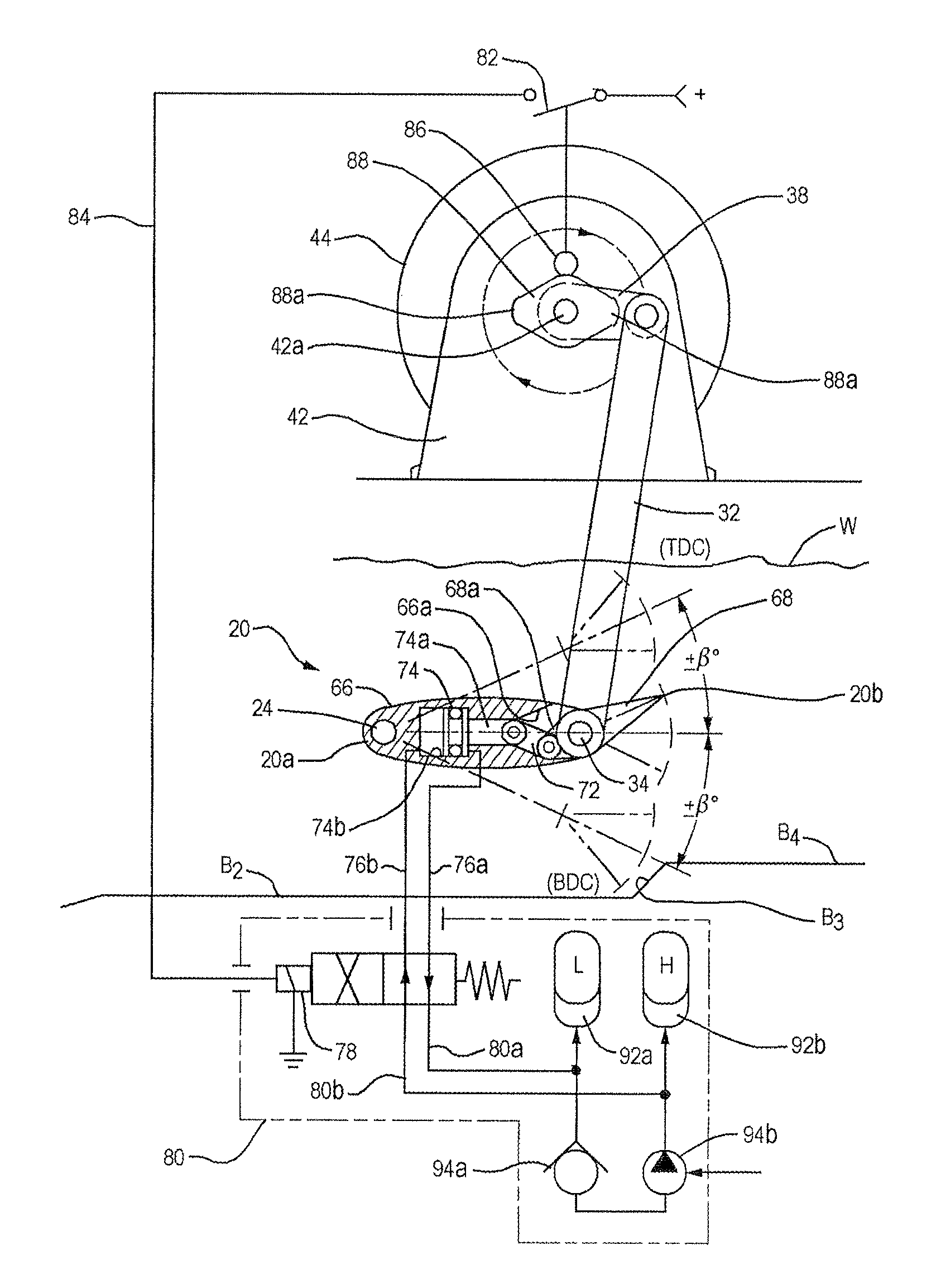
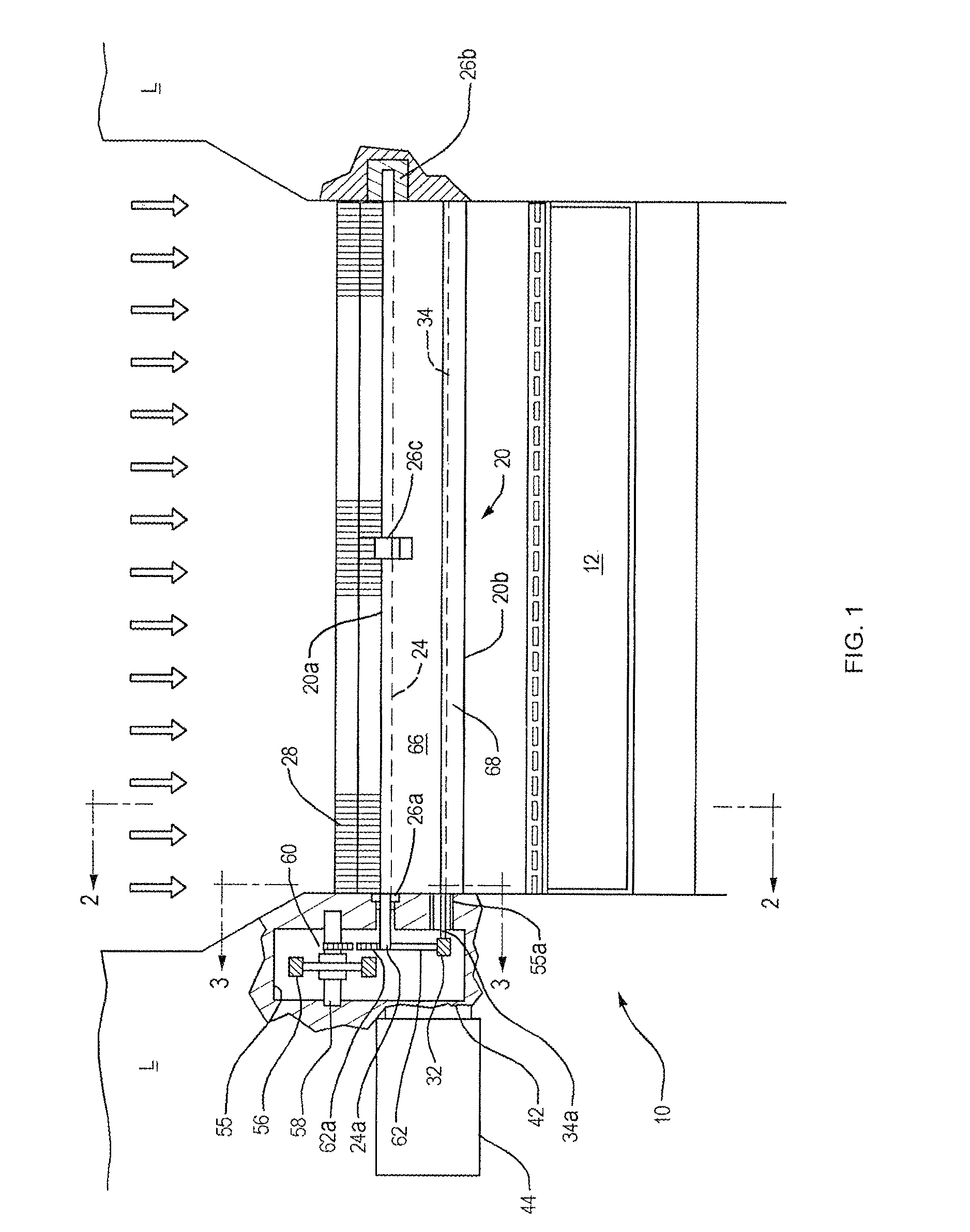
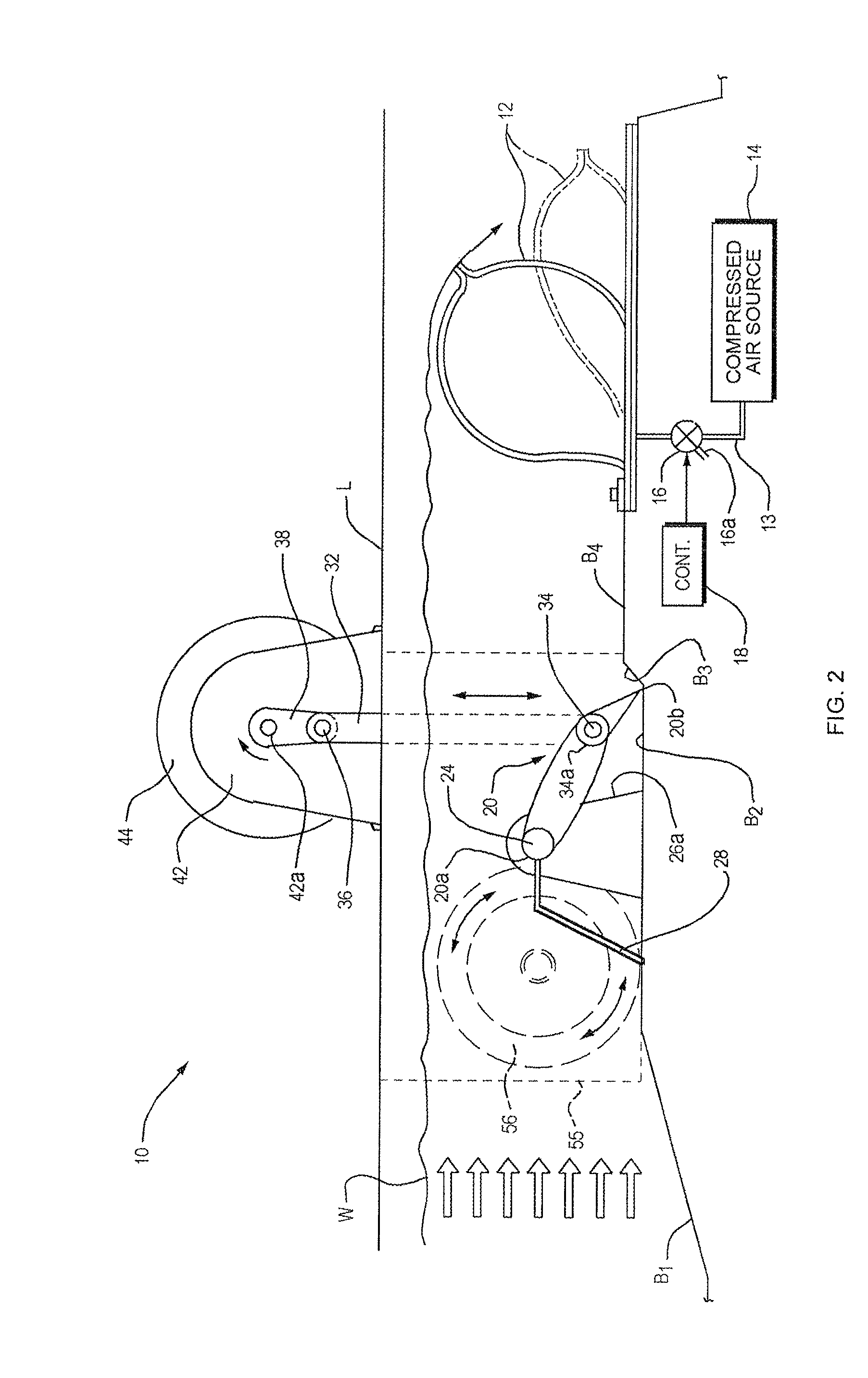
Refer now to FIGS. 1 and 2 of the drawings which show my apparatus, indicated generally at 10, as adapted to extract useful power from a relatively low pressure head, open shallow water source such as a river or stream, low head being defined as less than 10 meters. Apparatus 10 is mounted on the land L at opposite sides of a river whose water W flows in the direction of the arrows. Preferably, the bed of the river is prepared to receive the apparatus by profiling it is shown in FIG. 2 such that there is an incline B1 leading to a level area B2 directly under the apparatus. At the downstream edge of area B2, the bed steps up at B3 to a second level area B4 which is the site of a conventional, inflatable dam 12.

The interior of dam 12 is connected by a pipe 13 to a compressed air source 14, the flow of air through pipe 13 being controlled by a remote controlled valve 16. In order to increase the level of the water W over the bed B2, the valve 16...


PUM


Abstract

Power generation apparatus includes a wing-shaped blade having opposite sides, opposite ends and leading and trailing edges extending between those ends. A lift differential producing device in the blade produces a lift differential at the opposite sides of the blade and that device is switched so that one blade side or the other produces the greater lift. A blade shaft extends along an axis in the blade that is in close parallel relation to the leading edge of the blade and that shaft is fixed to move with the blade. Supports support the blade shaft so that the blade can be positioned in a fluid stream with the leading edge facing upstream and swing about the axis between first and second extreme positions on opposite sides of a neutral position, the blade shaft oscillating with the blade. A coordinating device coordinates the switching of the lift differential producing device with the swinging of the blade so that the switching occurs at the extreme positions of the blade. A method of generating power using the apparatus is also disclosed.

Description

BACKGROUND OF THE INVENTIONThis invention relates to power generation apparatus employing one or more blades which move under the influence of a fluid stream to produce an output force capable of performing useful work. For example, the apparatus may be used to power a pump or to reciprocate or rotate a shaft. The invention relates especially to such apparatus whose blade(s) oscillates instead of rotates in the presence of a wind or water stream to produce an output torque for driving an electric generator to provide grid quality power to a utility grid or to a remote off grid community, for example. A method for generating power in this fashion is also part of my invention.Conventional hydro-electric power generators usually comprise large rotating element water turbines requiring their own power house and extensive civil engineering works, and which require a large pressure head to be effective which, in turn, demands a high dam for creating this potential energy; the dam is also ...

Claims


Application Information

Patent Timeline
Patent Type & Authority Patents(United States)
IPC IPC(8): F03D9/00H02P9/04F03B13/00F03B13/10B64C9/00B64C11/28F03D5/06
CPCE02B9/00F03B13/086F03B17/062F03D9/008F03D11/02F05B2240/201F05B2240/214Y02E10/22Y02E10/28Y02E10/722Y02E10/725F03D9/007F03D9/12F03D13/22F03D15/00F03D15/10F03D9/255Y02E10/20Y02E10/30Y02E10/72Y02E60/16Y02E70/30Y02P80/10
Inventor BIRKESTRAND, ORVILLE J.
Owner BIRKESTRAND ORVILLE J
Why Eureka
Try Eureka