
Switched capacitor notch filter

a capacitor notch filter and switch capacitor technology, applied in the field of electronic notch filters, can solve the problems of undesirable offset in the sensor, inability to dynamically cancel the contribution of the buffer stage, and occupying the area of the output buffer,

Active Publication Date: 2011-08-02
ALLEGRO MICROSYSTEMS INC
View PDF14 Cites 108 Cited by
  • Summary
  • Abstract
  • Description
  • Claims
  • Application Information

AI Technical Summary

Benefits of technology

With this arrangement, the charge from the sampling capacitors is simultaneously averaged and transferred to the amplifier output during an averaging time period, thereby eliminating the need for conventional buffering between sampling and averaging stages of a notch filter and the associated drawbacks.
In some embodiments, a switched capacitor feedback network is coupled in parallel with the first feedback capacitor provided in the feedback arrangement with respect to the operational amplifier. The switched capacitor feedback network includes a second feedback capacitor and a respective set of switches. Such embodiments additionally provide low-pass filter functionality and component selection allows adjustment of the low pass filter cutoff frequency and DC gain.
According to another aspect of the invention, low pass filter functionality may be provided in embodiments in which a reference node is coupled the output of the operational amplifier. The described notch filter may be used in a chopper stabilized Hall Effect sensor to reduce or eliminate unwanted signal components, such as a modulated offset signal which arises as ripple.

Problems solved by technology

Offset in a sensor is undesirable as it may limit the minimum detectable signal of the sensor.
In addition the buffer stage may not be suited for dynamically cancelling its offset contribution to the circuit.
The charge distribution discrete time approach uses the second sampling stage as the charge redistribution averaging stage and also requires relatively large sampling capacitor sizes, such as on the order of 4-10 picofarads, and an output buffer for isolating the capacitors holding the averaged signal from the remainder of the circuit, which output buffer may also be area consuming and not suited for using dynamic offset cancellation techniques for removing its offset contribution to the circuit.
However, the accuracy of this approach highly depends on the integrating clocks phases relative to the chopper clock, and is also susceptible to the sampling non-ideal effects like charge injection and clock feed-through, such effects being reduced if averaging is used instead.

Method used


Image

  • Switched capacitor notch filter
  • Switched capacitor notch filter
  • Switched capacitor notch filter

Examples


Embodiment Construction

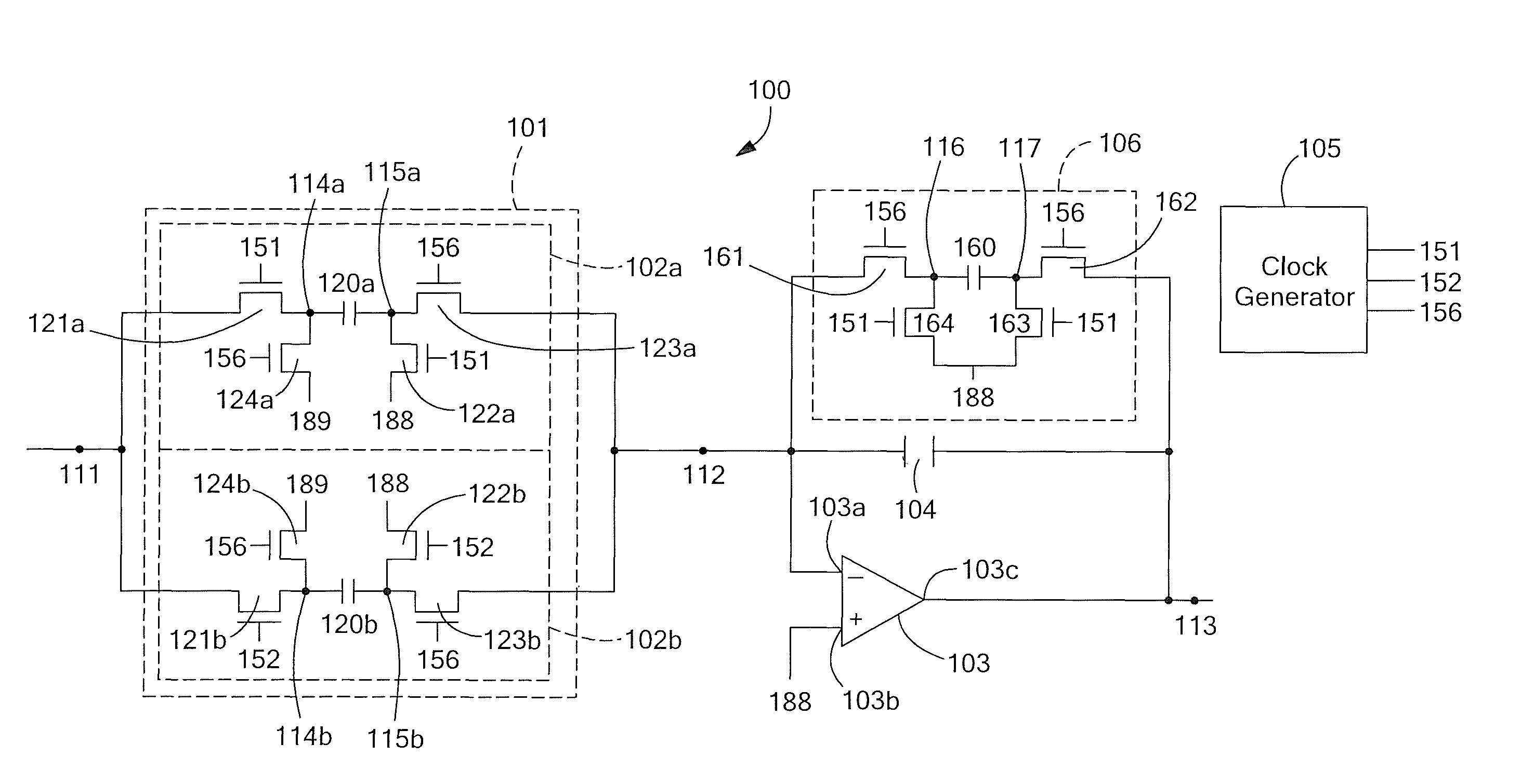
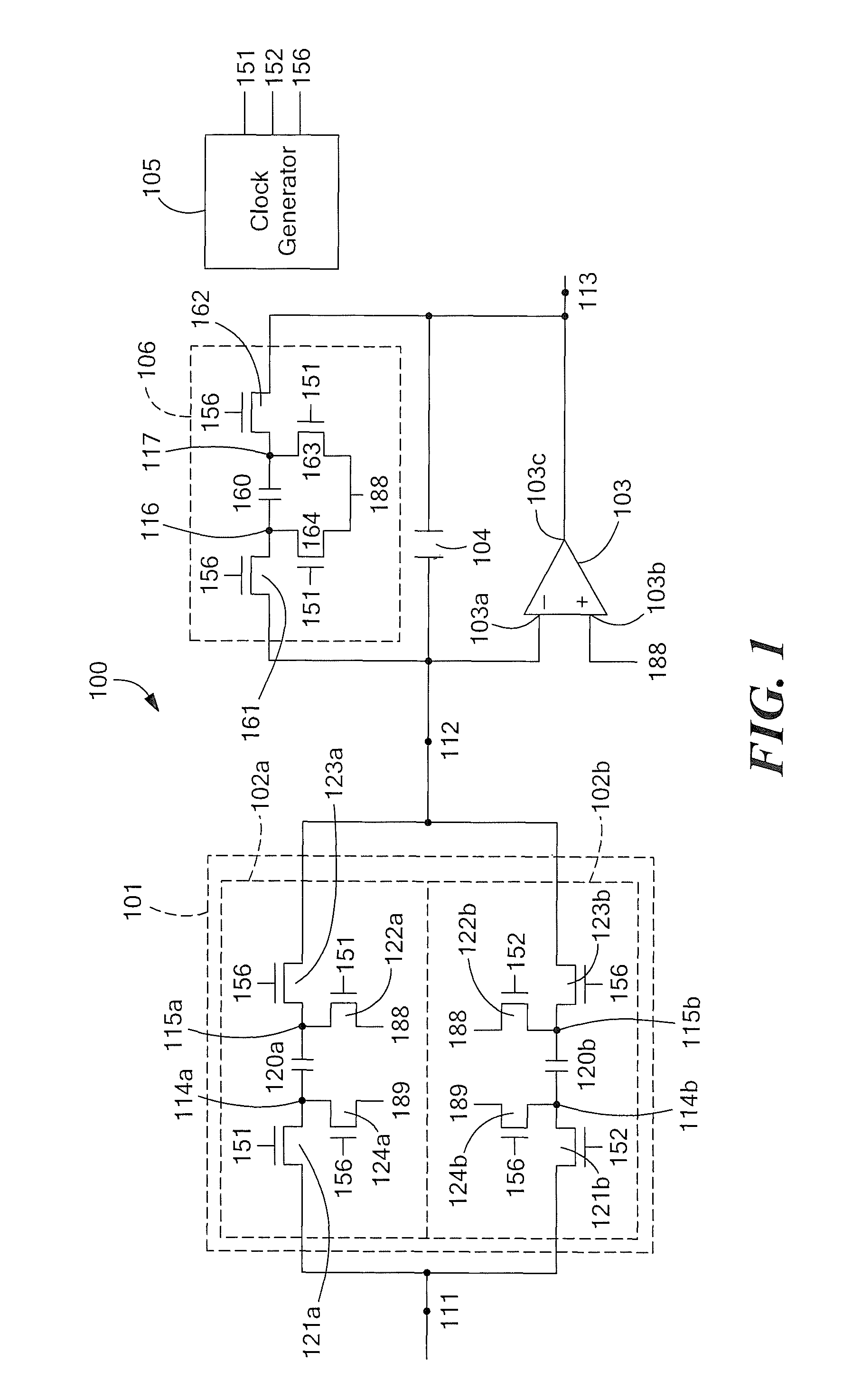
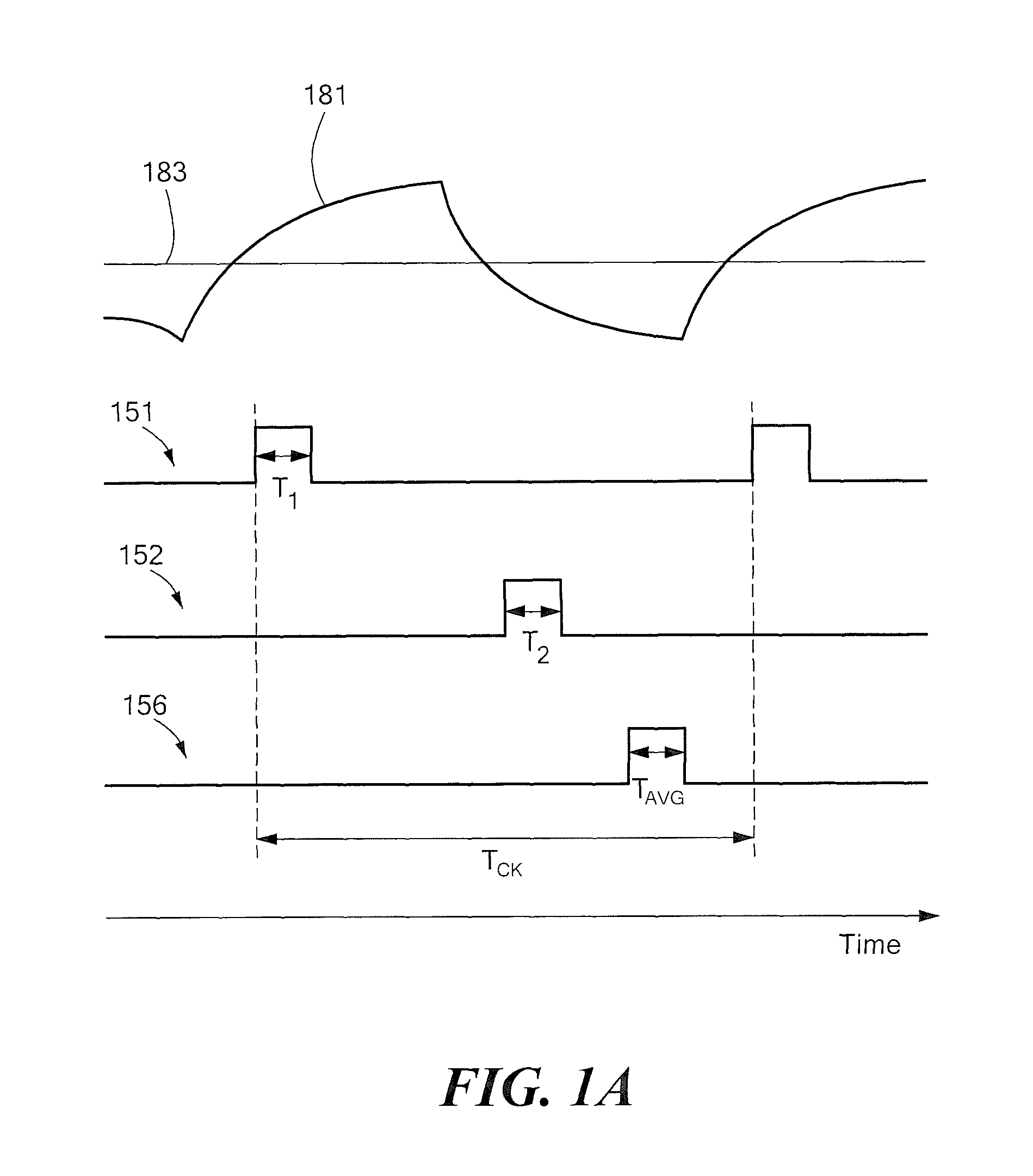
Referring to FIG. 1, a single-ended switched capacitor notch filter 100 includes an input terminal 111 adapted for receiving an input signal 181 (FIG. 1A). A sampling and averaging portion 101 of circuit 100 includes at least two switched capacitor sampling networks 102a, 102b. In the illustrative embodiment of FIG. 1, two switched capacitor sampling networks 102a, 102b are shown; however, as will become apparent from consideration of FIGS. 1B and 1D below, more than two such networks may be used.

Each switched capacitor sampling network 102a, 102b comprises a respective sampling capacitor and associated switches. More particularly, the first switched capacitor sampling network 102a includes a first sampling capacitor 120a and associated switches 121a, 122a, 123a, and 124a and the second switched capacitor sampling network 102b includes a second sampling capacitor 120b and associated switches 121b, 122b, 123b, and 124b. The first sampling capacitor 120a has a first terminal 114a coup...


PUM


Abstract

A switched capacitor notch filter for sampling an input signal using multiple sampling capacitors and multiple non-overlapping time periods. The charge from the sampling capacitors is averaged and transferred to the filter output during another non-overlapping time period.

Description

CROSS REFERENCE TO RELATED APPLICATIONSNot Applicable.STATEMENT REGARDING FEDERALLY SPONSORED RESEARCHNot Applicable.FIELD OF THE INVENTIONThis invention relates generally to electronic filters and, more particularly, to electronic notch filters which include sampling and averaging functions.BACKGROUND OF THE INVENTIONNotch filters are often used to remove unwanted signal components within a specific frequency range for a particular circuit. One application for a notch filter is in chopper stabilized Hall effect sensors, in which a notch filter, sometimes referred to as a sinc filter, may be used to remove unwanted components, such as a modulated offset signal component which arises as ripple, that result from the chopping operation without requiring a multi-pole filter approach that may result in unacceptable time delays to the sensor output signal. Offset in a sensor is undesirable as it may limit the minimum detectable signal of the sensor. One such arrangement is described in a ...

Claims


Application Information

Patent Timeline
Patent Type & Authority Patents(United States)
IPC IPC(8): H03K5/00
CPCH03H19/004
Inventor ROMERO, HERNAN D.
Owner ALLEGRO MICROSYSTEMS INC
Learn More