Heating apparatus, heating method, and computer readable storage medium

a technology of heating apparatus and heating method, which is applied in the direction of lighting and heating apparatus, drying machines, manufacturing tools, etc., can solve the problems of inability to use technique and impaired uniform thermal processing, and achieve the effect of improving the uniformity of substrate-to-substrat temperatur

Active Publication Date: 2011-08-09
TOKYO ELECTRON LTD
View PDF201 Cites 401 Cited by
  • Summary
  • Abstract
  • Description
  • Claims
  • Application Information

AI Technical Summary

Benefits of technology

[0027]According to the present invention, when the substrate on the plural protrusions is attracted toward the heating plate by suction through the suction holes, the second gas is supplied to the gap between the heating plate and the substrate. Therefore, the first gas, which flows above the substrate and may include the volatile substances and / or the sublimated substances, is prevented from flowing into the gap, thereby preventing the substances from being condensed / precipitated on the inside walls of the suction holes. As a result, a suction force through the suction holes is prevented from being reduced by condensation / precipitation of volatile substances and / or sublimated substances in the suction holes, thereby improving substrate-to-substrate temperature uniformity as well as in-substrate temperature uniformity.

Problems solved by technology

As a result, the substrate 103 may no longer be attracted and thus uniform thermal processing is impaired.
However, this technique cannot be employed when the edge area of a back surface of the substrate is contaminated by a resist solution since the contaminated edge area contacts a top surface of the heat plate so as to produce particles from the resist.

Method used


Image

  • Heating apparatus, heating method, and computer readable storage medium
  • Heating apparatus, heating method, and computer readable storage medium
  • Heating apparatus, heating method, and computer readable storage medium

Examples


first embodiment

[0042]A heating apparatus according to a first embodiment of the present invention is preferably applicable to a coater / developer that spin-coats a film such as a resist film or the like on a substrate, for example, a semiconductor wafer (simply referred to as wafer W, hereinafter) and develops the spin-coated film.

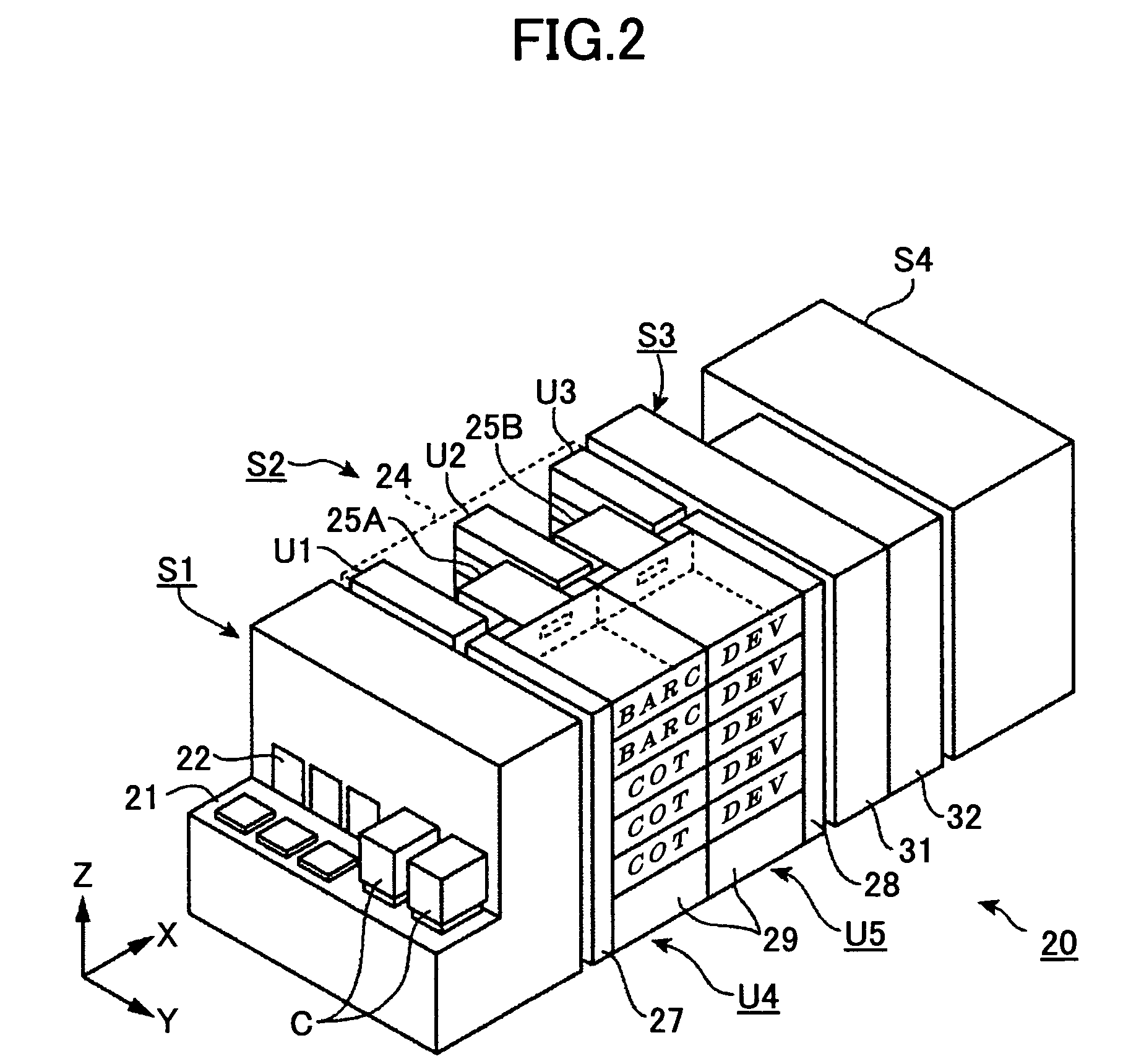
[0043]First, a coater / developer 20 is described in reference to FIGS. 2 and 3. As shown, the coater / developer 20 includes a cassette stage portion S1 for transferring wafers W (FIG. 4) in a substrate cassette C. The cassette stage portion S1 has a substrate cassette stage 21 on which plural substrate cassettes C can be placed, doors 22 corresponding to the plural substrate cassettes C placed on the substrate cassette stage 21, and a transfer mechanism 23 that transfers the wafers W from / to the substrate cassettes C through the doors 22. By the way, each of the substrate cassettes C can house plural wafers, for example, 13 wafers.

[0044]In addition, the coater / developer 20 ...

second embodiment

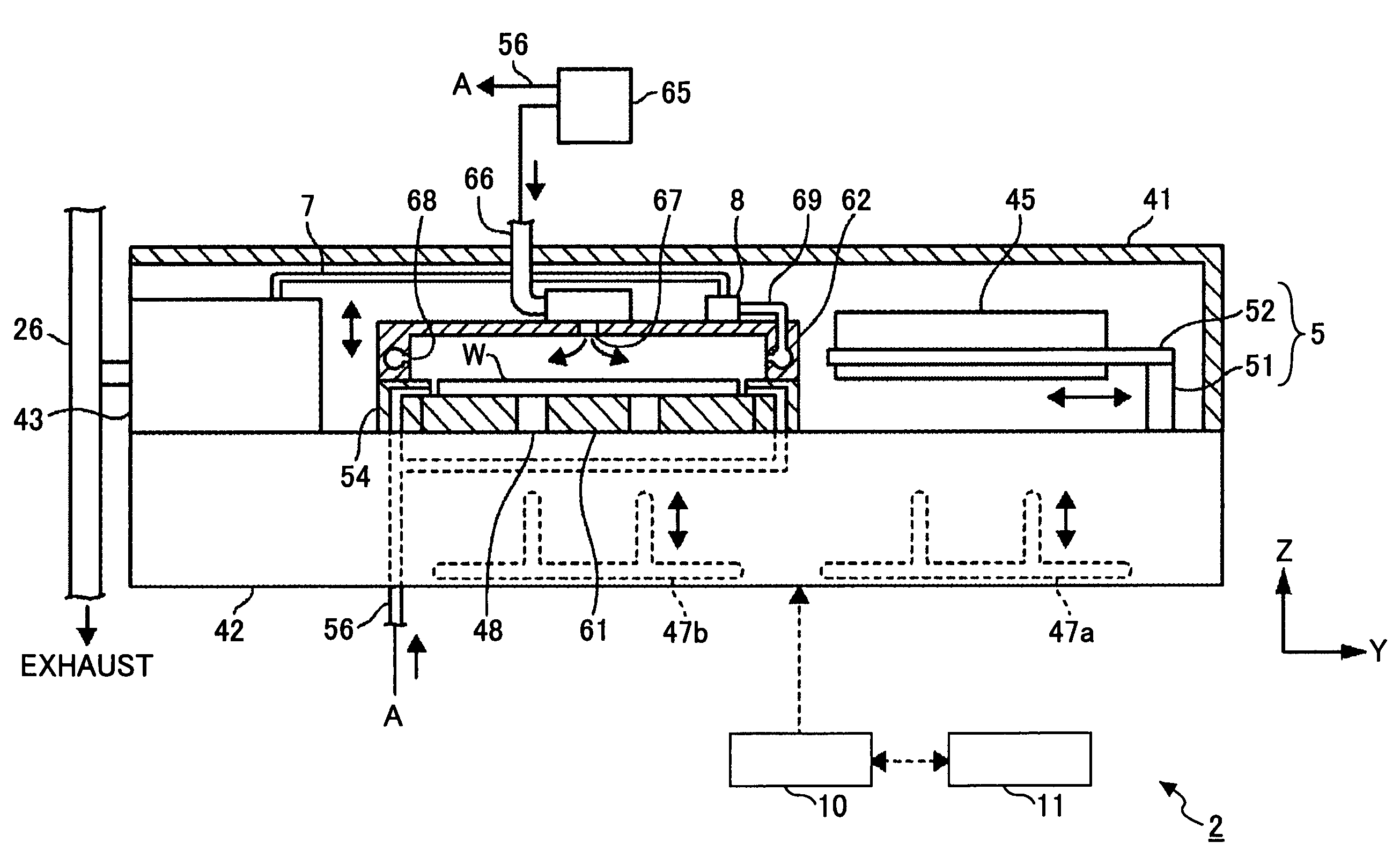
[0074]Next, a heating apparatus according to a second embodiment of the present invention is explained in reference to FIGS. 9 and 10. The explanation below is focused on the difference between the heating apparatus according to the second embodiment and the heating apparatus 2 according to the first embodiment, specifically the difference in the heating plate and the lid body, while repetitive explanations about the same members or components as these in the first embodiment are omitted.

[0075]Referring to FIG. 9, a heating apparatus 3 according to the second embodiment does not include a ring member, which exists as the ring member 54 in the heating apparatus 2 according to the first embodiment. Because of lacking the ring member, the gas supplying openings 57, which are provided in the ring member 54 in the first embodiment, are formed in a heating plate 61a. In addition, the gas supplying openings 57 are arranged so as to be along the circumferential back portion of the wafer W t...

modification example

[0078]The gas supplying opening 57 formed in the heating plate 61a may be shaped into an annular groove, which is described in reference to FIG. 12. As shown, a heating plate 61b has a ring shaped gas supplying opening 57a outside the suction holes 83 and the gas supplying opening 57a is connected at a portion of the bottom to the gas supplying conduit 56. Although only one gas supplying conduit 56 is connected to the bottom of the gas supplying opening 57a in FIG. 12, plural gas supplying conduits 56 may be connected to corresponding positions of the bottom of the gas supplying opening 57a at equal angular intervals.

[0079]In such a heating plate 61b, the wafer W is attracted by suction and thermally processed in the same manner as performed with the heating plate 61a.

[0080]In the above embodiments and the example, the purified gas is supplied to the gap between the back surface of the wafer W and the heating plate 61, 61a, 61b along substantially converging radial directions, i.e....


PUM

PropertyMeasurementUnit
temperatureaaaaaaaaaa
timeaaaaaaaaaa
volatileaaaaaaaaaa

Abstract

A disclosed heating apparatus for heating a substrate on which a film is coated includes a process chamber having a gas supply opening for supplying a first gas to the process chamber and a gas evacuation opening for evacuating the first gas from the process chamber; a heating plate that is arranged in the process chamber and includes a heating element for heating the substrate; plural protrusions arranged on the heating plate so as to support the substrate; plural suction holes formed in the heating plate so as to attract by suction the substrate toward the heating plate; and a gas inlet adapted to supply a second gas to a gap between the heating plate and the substrate supported by the plural protrusions.

Description

BACKGROUND OF THE INVENTION[0001]1. Field of the Invention[0002]The present invention relates to a heating apparatus and a heating method, which are for heating a substrate on which a film is coated, and a computer readable storage medium storing a computer program for causing the heating apparatus to perform the heating method.[0003]2. Description of the Related Art[0004]A coater / developer for coating an organic material film such as a resist film or the like on a substrate and developing the film is provided with a heating apparatus for heating and / or cooling the substrate.[0005]As an example of such a heating apparatus, a substrate heating apparatus 101 is described in reference to FIG. 1. In the substrate heating apparatus 101, a substrate 103 is placed on a heating plate 102 and heated by a heater 104 embedded in the heating plate 102. During heating the substrate 103, nitrogen is supplied toward the substrate 103 so as to purge volatile substances such as organic solvents from...

Claims


Application Information

Patent Timeline
Patent Type & Authority Patents(United States)
IPC IPC(8): F26B11/02
CPCH01L21/67109H01L21/6875H01L21/6838H01L21/324H01L21/02
Inventor KAWAJI, TATSUYASAKAI, YUICHIKANEDA, MASATOSHI
Owner TOKYO ELECTRON LTD
Why Eureka
Try Eureka