Parking brake and method for operating same

a technology for parking brakes and brakes, applied in braking systems, instruments, analogue processes for specific applications, etc., can solve problems such as insufficient precision, insufficient operation, and inability to meet the required level of reliability of brake-by-wire brake systems

Active Publication Date: 2011-08-09
CONTINENTAL TEVES AG & CO OHG
View PDF19 Cites 31 Cited by
  • Summary
  • Abstract
  • Description
  • Claims
  • Application Information

AI Technical Summary

Benefits of technology

[0012]The method according to aspects of the invention relates to the fact that the piston is arranged in a brake housing and moves, like the spindle and the nut of the actuator, in brake fluid. A hydraulic brake pressure which is variable as a function of the position of the brake pedal of the motor vehicle is correspondingly present at the piston, wherein the brake pedal is operated by the driver of the motor vehicle. The method according to aspects of the invention makes use of the realization that the brake-application force which is set is superimposed additively on the hydraulic admission pressure which prevails in the system, with the result that the sum of the forces of the hydraulic admission pressure and the brake-application force which is set yields a resulting brake-application force. For the release, the hydraulic admission pressure should be noted in particular with respect to the detection of the application point. Accordingly, the accuracy of the setting of the brake-application force or of the brake-application clearance can be increased by virtue of the fact that, according to aspects of the invention, the hydraulic admission pressure which is currently present in the system is taken into account during the application of the parking brake and / or the hydraulic admission pressure which was present when the brake had previously been applied is taken into account during the release of the parking brake.
[0014]Such a method has the advantage that the maximum current value can be determined from the desired brake-application force, the hydraulic admission pressure, a geometric value and the idling current, and merely a single parameter which is stored, for example, in a characteristic diagram. The calculation of the maximum current value can therefore be carried out easily and quickly.
[0015]Furthermore, the accuracy of the setting of the brake-application force can be improved if, in addition, during the determination of the maximum current value a temperature-dependent correction value, which preferably comprises the temperature of the direct-current motor at the start of the brake-application process, is taken into account as a third, additive component, and / or a correction value which is dependent on the number of previous activations of the parking brake is taken into account as a fourth component, which is also additive. Taking into account these corrections has the advantage that temperature effects and wear of the mechanical components are included in the determination of the maximum current value which is to be reached for the necessary brake-application force.
[0016]It is also preferred that when the brake has been applied and / or released by means of a motor model, the control unit continuously determines an activation travel which has been carried out by the direct current motor. The activation travel of the direct current motor also corresponds here to the travel which the nut carries out on the spindle which is driven by the motor, or of the pistons. Owing to this advantageous procedure, it is very easy, as described below, to take into account the hydraulic admission pressure during, for example, the calibration of the piston position to the application point.
[0018]As has already been stated above, the hydraulic admission pressure which is present when the brake-application force is implemented must also be taken into account, the brake-application force which is set being superimposed on said hydraulic admission pressure. By means of the hydraulic admission pressure it is possible, as shown below, to calibrate the piston position which is determined only using a motor model to the application point or to the point at the end of the brake-application process. This is a particularly simple way of calibrating positions and it corresponds to accurate open-loop or closed-loop control of the actuator movement during the application or release of the brake.

Problems solved by technology

A basic problem of contemporary open-loop / closed-loop control systems of parking brakes is that the brake-application force is not measured directly, for reasons of cost, but instead is determined indirectly from other parameters.
However, as is recognized nowadays, the known methods do not operate precisely enough, with the result that the brake-by-wire brake system frequently does not exhibit the required level of reliability.

Method used


Image

  • Parking brake and method for operating same
  • Parking brake and method for operating same
  • Parking brake and method for operating same

Examples


Embodiment Construction

1. Description of the Parking Brake According to Aspects of the Invention

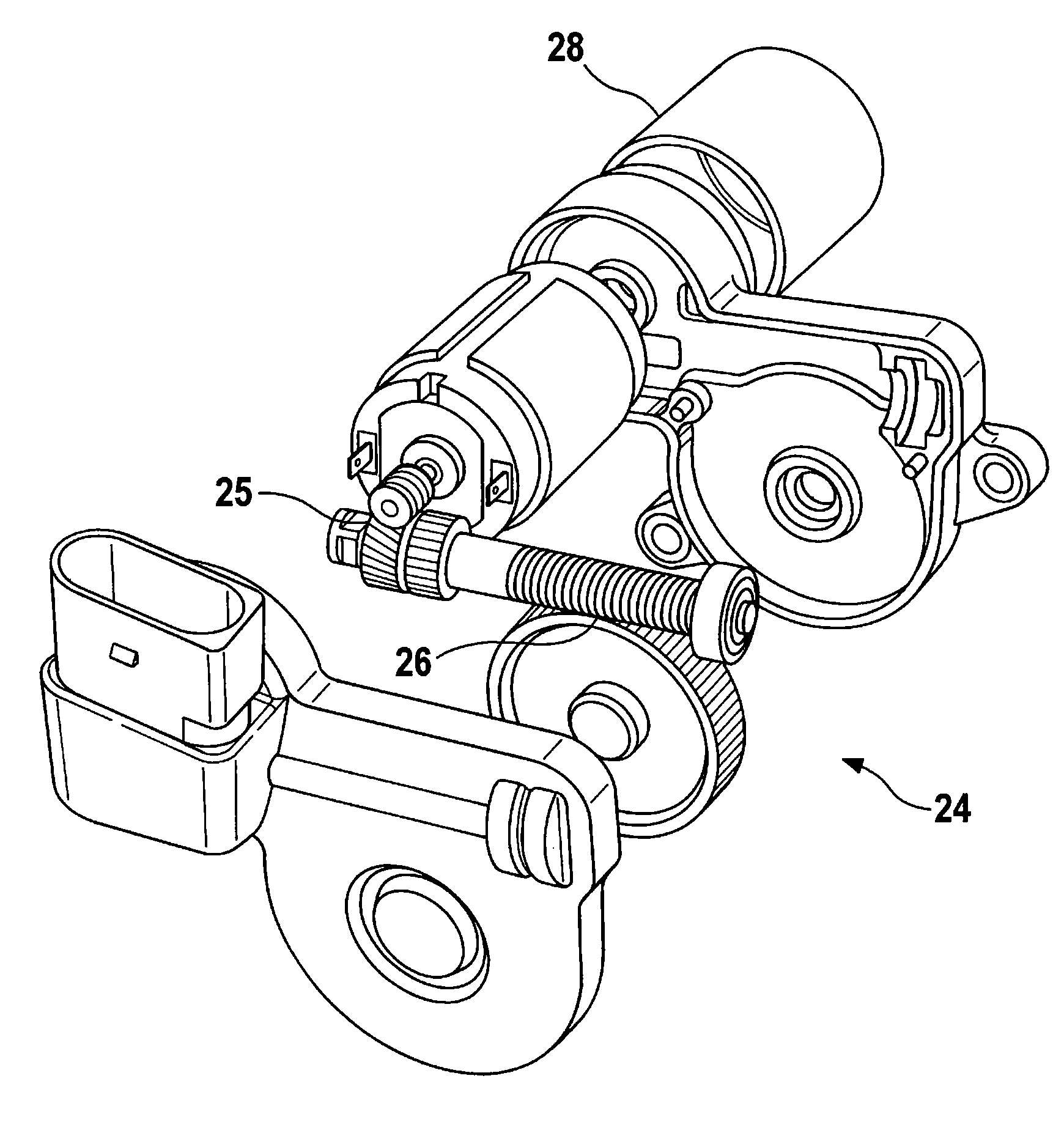
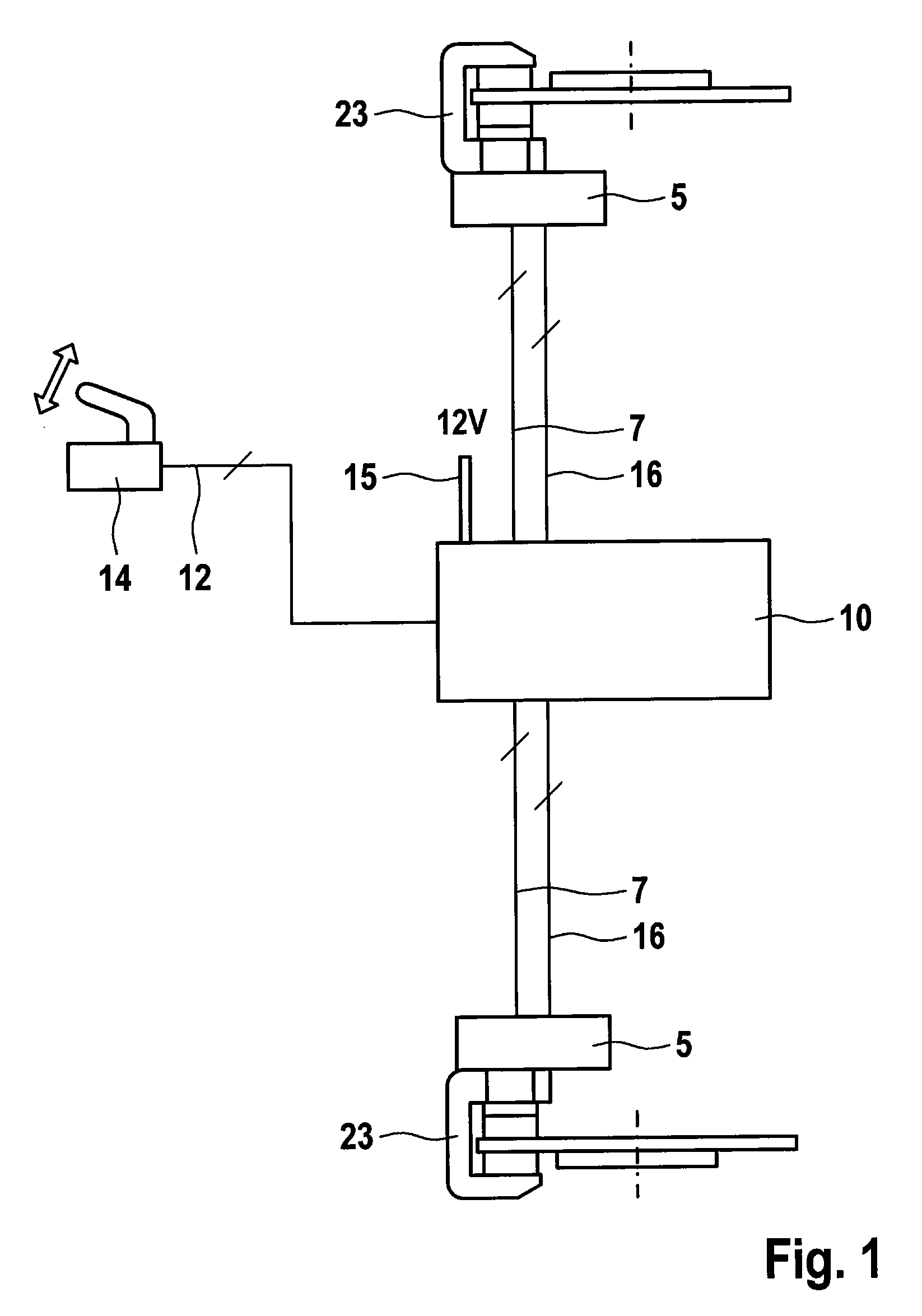
[0033]The parking brake according to aspects of the invention which is illustrated in FIG. 1 for a motor vehicle has, for each wheel, an actuator 5 which is respectively connected to a control unit 10 via an open-loop / closed-loop control line 7. FIG. 1 also shows the connection of the control unit 10 via an (if appropriate multiple) open-loop / closed-loop control line 12 to the activation switch 14 of the parking brake with which the application or release of the parking brake can be initiated by the driver of the motor vehicle. The control unit 10 has a voltage supply 15 and is also connected in each case to the actuators 5 by a line 16 which transmits the temperature of the respective actuator 5 to the control unit 10.

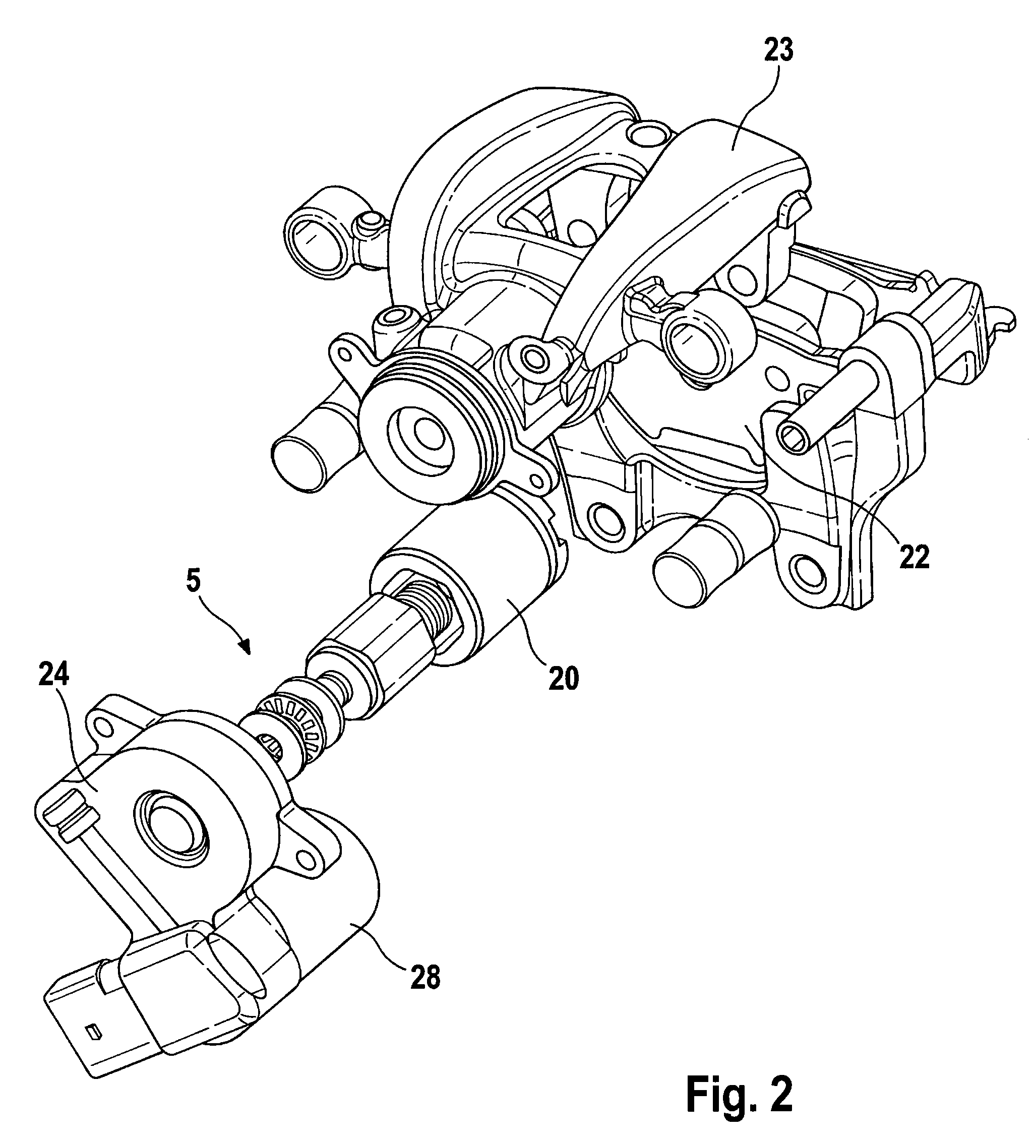
[0034]FIGS. 2 and 3 show that each actuator 5 is provided with a spindle which is located in the hydraulically operated brake piston 20 and on which the rotationally secured nut moves with the ro...


PUM


Abstract

A parking brake having an actuator, wherein the actuator is driven with a direct current motor which can be operated in two directions and which moves a piston of the actuator and, via a self-locking gear mechanism of the actuator, at least one brake shoe for applying or releasing the parking brake. A control unit for performing open-loop or closed-loop control of the movement of the direct current motor is also provided. During open-loop or closed-loop control of the movement of the direct current motor for applying and / or releasing the parking brake, the control unit takes into account a hydraulic admission pressure which is currently present at the piston if the brake is applied or was present at the piston if the brake has been released when it had previously been applied. A corresponding method for operating such a parking brake is also disclosed.

Description

CROSS REFERENCE TO RELATED APPLICATIONS[0001]This application is the U.S. national phase application of PCT International Application No. PCT / EP2008 / 064356, filed Oct. 23, 2008, which claims priority to German Patent Application No. 10 2007 051 078.2, filed Oct. 24, 2007 and German Patent Application No. 10 2008 052 845.5, filed Oct. 23, 2008, the contents of such applications being incorporated by reference herein.FIELD OF THE INVENTION[0002]The present invention relates to a parking brake having an actuator, wherein the actuator is driven with a direct current motor which can be operated in two directions and which moves a piston of the actuator and hereby, via a self-locking gear mechanism of the actuator, at least one brake shoe for applying or releasing the parking brake, wherein a control unit is provided for performing open-loop or closed-loop control of the movement of the direct current motor, and also to a method for operating a parking brake of this type.BACKGROUND OF THE...

Claims


Application Information

Patent Timeline
Patent Type & Authority Patents(United States)
IPC IPC(8): F16D55/26B60T8/24
CPCB60T13/588B60T17/221B60T13/746
Inventor MARON, CHRISTOFSCHUMANN, MARCUSATTALLAH, FAOUZISCHNEIDER, HEINZ-ANTON
Owner CONTINENTAL TEVES AG & CO OHG
Why Eureka
Try Eureka