Hydraulic pressure supply unit of continuously variable transmission

a technology of continuously variable transmission and pressure supply unit, which is applied in the direction of gearing control, belt/chain/gearing, gearing element, etc., can solve the problems of pressure supplied to the primary sheave, unnecessary downshift, and effective diameter reduction of the effective diameter of the primary sheave, and achieve the effect of increasing the number of components

Inactive Publication Date: 2011-08-09
TOYOTA JIDOSHA KK
View PDF10 Cites 12 Cited by
  • Summary
  • Abstract
  • Description
  • Claims
  • Application Information

AI Technical Summary

Benefits of technology

[0012]The present invention aims to implement a fail-safe function while suppressing an increase in the number of components.
[0014]According to the above-described configuration, the switching valve switches between the first state where the hydraulic pressure controlled by the second solenoid valve is supplied to the primary pulley and the second state where the hydraulic pressure supplied to a different device from the primary pulley is supplied also to the primary pulley. In the first state, the gear ratio of the continuously variable transmission can be controlled to be optimal. In the second state, the hydraulic pressure supplied to the different device from the primary pulley is supplied also to the primary pulley. Accordingly, when the hydraulic pressure supplied to the primary pulley is decreased due to some irregular conditions in the first state, the switching valve is switched from the first state to the second state, so that the hydraulic pressure supplied to the primary pulley can be maintained. Furthermore, in the first state, the hydraulic pressure obtained by decreasing a line pressure is supplied to the friction engagement element (a clutch or a brake). In the second state, the hydraulic pressure controlled by the first solenoid valve is supplied to the friction engagement element. Consequently, when the friction engagement element is engaged, the hydraulic pressure controlled by the first solenoid valve is supplied to the friction engagement element, which allows the friction engagement element to be engaged such that the impact at the time of engagement is reduced. When the friction engagement element is engaged, the hydraulic pressure supplied to the primary pulley is maintained by the orifice. Accordingly, unnecessary downshift of the continuously variable transmission can be prevented from occurring. After the friction engagement element is engaged, the hydraulic pressure obtained by decreasing a line pressure is supplied to the friction engagement element, which allows the friction engagement element to be held in the engaged state such that the power output from the driving source is transmitted to wheels. Thus, the fail-safe function for the hydraulic pressure supplied to the primary pulley can be implemented using the switching valve for switching the hydraulic pressure supplied to the friction engagement element. Accordingly, the fail-safe function can be achieved without the need to provide a dedicated valve having only the fail-safe function. Consequently, the hydraulic pressure supply unit of the continuously variable transmission capable of implementing a fail-safe function while suppressing an increase in the number of components can be provided.
[0016]According to the above-described configuration, in the case where the hydraulic pressure supplied to the primary pulley is decreased due to some irregular conditions, the hydraulic pressure supplied to the secondary pulley is supplied also to the primary pulley, so that the fail-safe function can be implemented.
[0018]According to the above-described configuration, when the friction engagement element is changed from the disengaged state to the engaged state, the hydraulic pressure controlled by the first solenoid valve is supplied to the friction engagement element. This allows the friction engagement element to be engaged such that the impact at the time of engagement is reduced. Furthermore, when the continuously variable transmission downshifts in the state where the continuously variable transmission is controlled so as not to downshift, the hydraulic pressure supplied to a different device from the primary pulley is supplied also to the primary pulley. Consequently, in the case where the hydraulic pressure supplied to the primary pulley is decreased due to some irregular conditions, the hydraulic pressure supplied to the primary pulley can be maintained. Therefore, unintentional downshift can be prevented from proceeding.

Problems solved by technology

In accordance with an increase in the effective diameter of the primary pulley, the groove width of the secondary pulley is increased and the effective diameter thereof is decreased, which leads to upshifting.
In accordance with a decrease in the effective diameter of the primary pulley, the groove width of the secondary pulley is narrowed and the effective diameter thereof is increased, which leads to downshifting.
Accordingly, when the hydraulic pressure supplied to the primary sheave of the primary pulley is decreased, for example, due to some irregular conditions, unnecessary downshift may occur.
However, the valve having only a fail-safe function as disclosed in Japanese Patent Laying-Open No. 2004-169895 is additionally provided, which poses a problem that the number of components increases.

Method used


Image

  • Hydraulic pressure supply unit of continuously variable transmission
  • Hydraulic pressure supply unit of continuously variable transmission
  • Hydraulic pressure supply unit of continuously variable transmission

Examples


Embodiment Construction

[0028]The embodiments of the present invention will be hereinafter described with reference to the accompanying drawings, in which the same components are designated by the same reference characters and have the same names and functions. Accordingly, detailed description thereof will not be repeated.

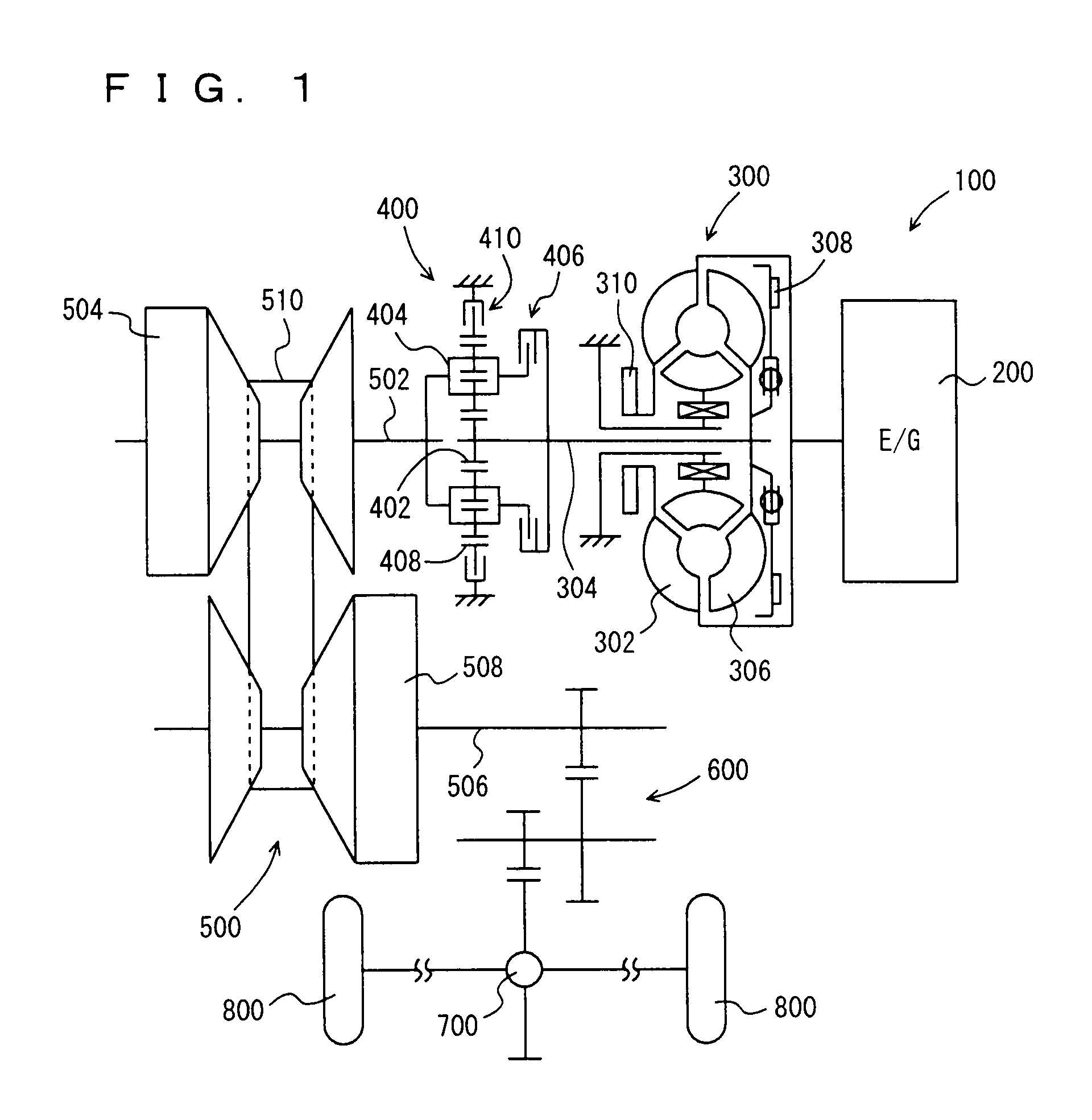
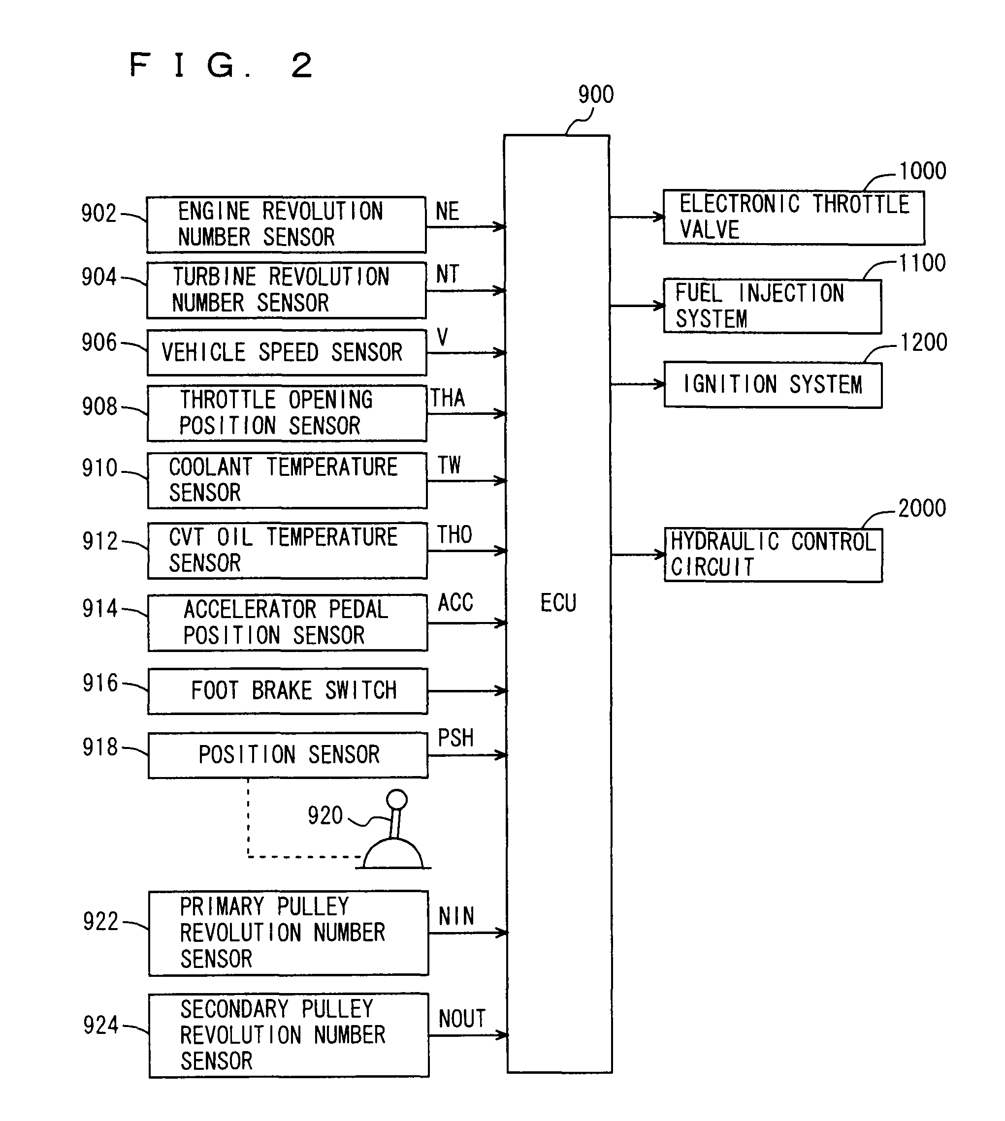
[0029]Referring to FIG. 1, the output power of an engine 200 of a power train 100 mounted in the vehicle is input to a continuously variable transmission 500 having a forward and backward movement switching device 400 through a torque converter 300. The output power of continuously variable transmission 500 is transmitted to a reduction gear 600 and a differential gear 700, and distributed to a driving wheel 800 on each of the right and left sides. Power train 100 is controlled by an ECU (Electronic Control Unit) 900 described below. In place of or in addition to engine 200, a motor may be used as a driving source.

[0030]Torque converter 300 includes a pump impeller 302 coupled to the cra...


PUM


Abstract

A control valve switches between the (A) state where the first oil passage to which a hydraulic pressure obtained by decreasing a line pressure is supplied is in communication with the fifth oil passage for supplying the hydraulic pressure to a forward clutch or a reverse brake and the third oil passage to which a hydraulic pressure controlled by an SLP linear solenoid valve is supplied is in communication with the sixth oil passage for supplying the hydraulic pressure to a primary pulley, and the (B) state where the second oil passage to which a hydraulic pressure controlled by an SLT linear solenoid valve is supplied is in communication with the fifth oil passage and the fourth oil passage for supplying the hydraulic pressure to a secondary pulley is in communication with the sixth oil passage. The fourth oil passage has an orifice.

Description

[0001]This nonprovisional application is based on Japanese Patent Application No. 2008-321196 filed on Dec. 17, 2008, with the Japan Patent Office, the entire contents of which are hereby incorporated by reference.BACKGROUND OF THE INVENTION[0002]1. Field of the Invention[0003]The present invention relates to a hydraulic pressure supply unit of a continuously variable transmission (CVT), and particularly to a friction engagement element to be engaged during the vehicle running and a hydraulic circuit used for supplying hydraulic pressure to a primary pulley.[0004]2. Description of the Background Art[0005]A continuously variable transmission which can continuously change a gear ratio is conventionally known. In the continuously variable transmission, for example, a metal belt or a chain is held by each of a primary pulley and a secondary pulley. Also in the continuously variable transmission, the gear ratio is changed generally by changing the hydraulic pressure supplied to the prima...

Claims


Application Information

Patent Timeline
Patent Type & Authority Patents(United States)
IPC IPC(8): F16H59/00
CPCF16H61/12F16H61/66259F16H2061/1264
Inventor OGATA, YUSUKE
Owner TOYOTA JIDOSHA KK
Why Eureka
Try Eureka