Cylindrical target with oscillating magnet for magnetron sputtering

a cylindrical target and oscillating magnet technology, applied in the field of cylindrical targets, can solve the problems of severe erosion, uneven wear of the target along its length, and uneven erosion between the end portions, so as to improve the uniformity of the erosion pattern of the cylindrical sputtering targ

Active Publication Date: 2011-08-09
GENERAL PLASMA +1
View PDF18 Cites 7 Cited by
  • Summary
  • Abstract
  • Description
  • Claims
  • Application Information

AI Technical Summary

Benefits of technology

[0006]It has now been found that the uniformity of the erosion pattern from a cylindrical sputtering target can be improved by causing the magnet within the target to oscillate axially of the target. In some embodiments the motion of the magnet is a function of, and derived from, the rotation of the target, such that the motion of the magnet and the rotation of the target happen simultaneously. In further embodiments, the magnet is oscillated in an asynchronous manner with respect to rotation of the target. In other embodiments, the magnet is movable manually.
[0007]Hence, in some embodiments, the invention relates to a cathode target assembly for use in sputtering target material onto a substrate such as glass. The assembly comprises a generally cylindrical target, and means for rotating the target about its axis during a sputtering operation. An elongated magnet is carried within the target for generation of a plasma-containing magnetic field exterior to but adjacent the target. A framework is provided for supporting the magnet against rotation within the target but enabling the magnet to move axially within the target. A power train is provided for causing the magnet to oscillate along its length axially of the target in a substantially asynchronous manner to promote generally uniform target utilization along its length. In some embodiments, the magnet is oscillated in response to rotation of the target.

Problems solved by technology

Unfortunately, it has been found that the targets do not wear uniformly and evenly along their lengths as material is sputtered from the targets' outer surfaces.
The erosion that takes place between their end portions similarly is not uniform; although some uniformity of erosion is experienced nearer the center of the target, severe erosion occurs near the target ends.

Method used


Image

  • Cylindrical target with oscillating magnet for magnetron sputtering
  • Cylindrical target with oscillating magnet for magnetron sputtering
  • Cylindrical target with oscillating magnet for magnetron sputtering

Examples


Embodiment Construction

[0021]The following detailed description is to be read with reference to the drawings, in which like elements in different drawings have like reference numerals. The drawings, which are not necessarily to scale, depict selected embodiments and are not intended to limit the scope of the invention. Skilled artisans will recognize that the examples provided herein have many useful alternatives that fall within the scope of the invention.

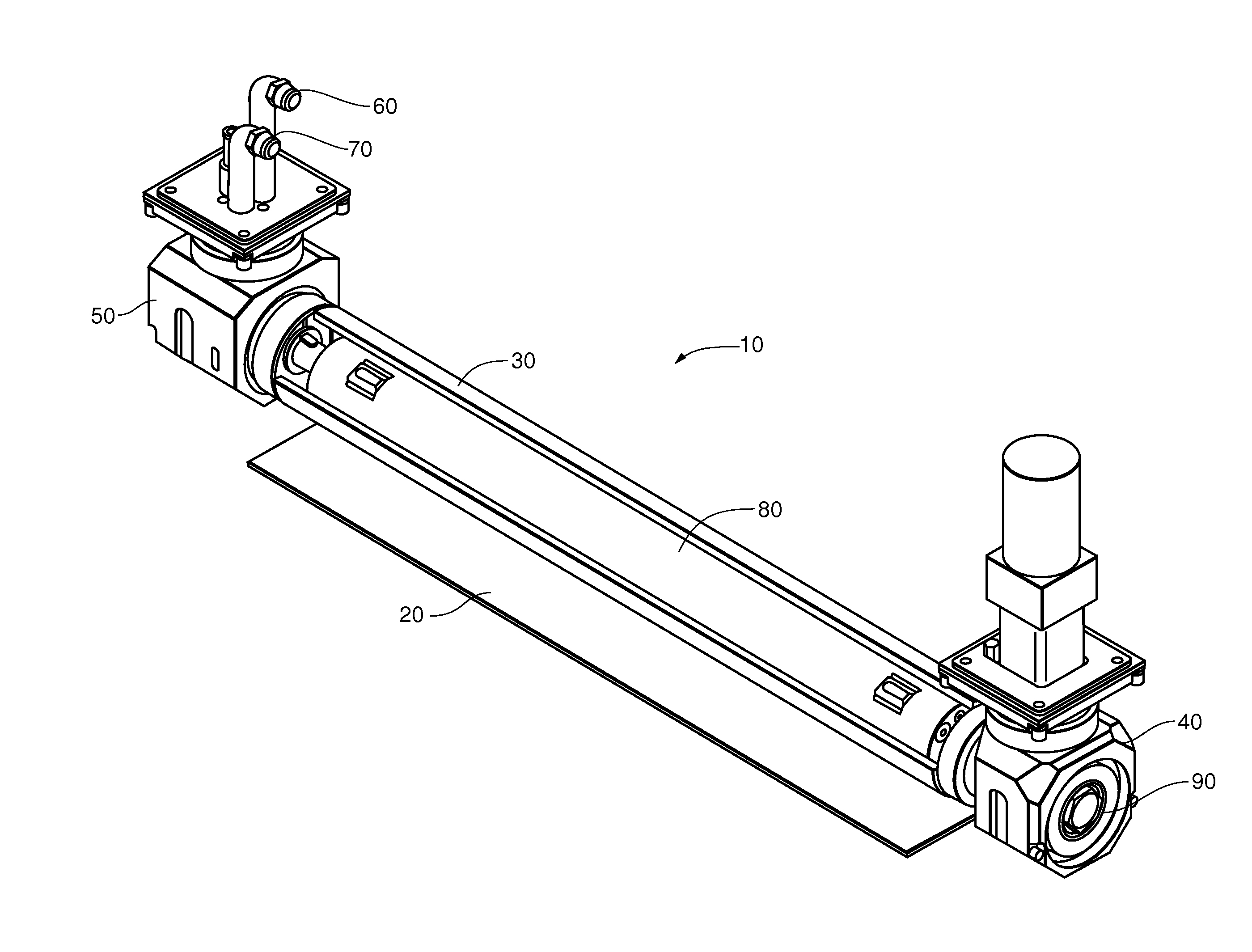
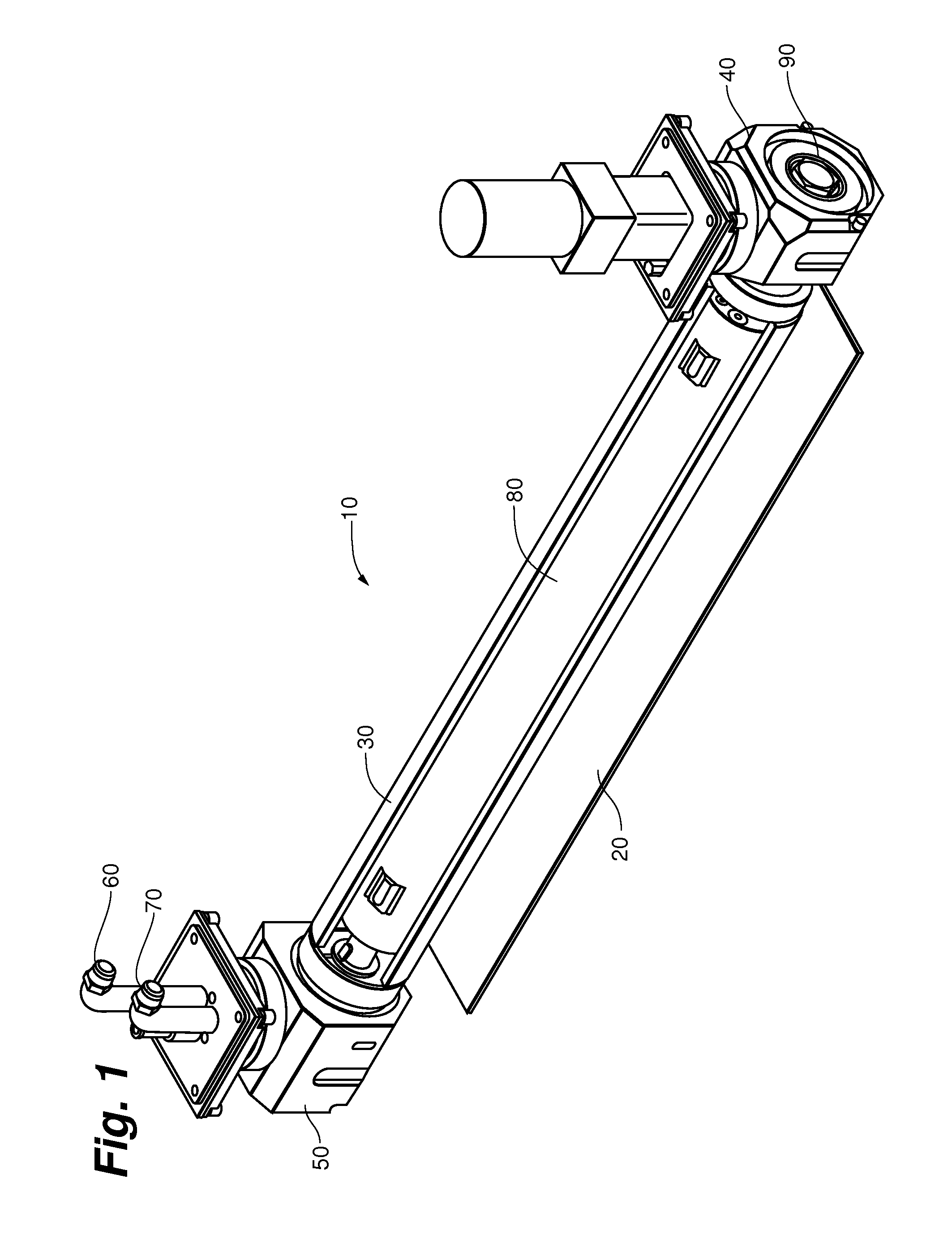
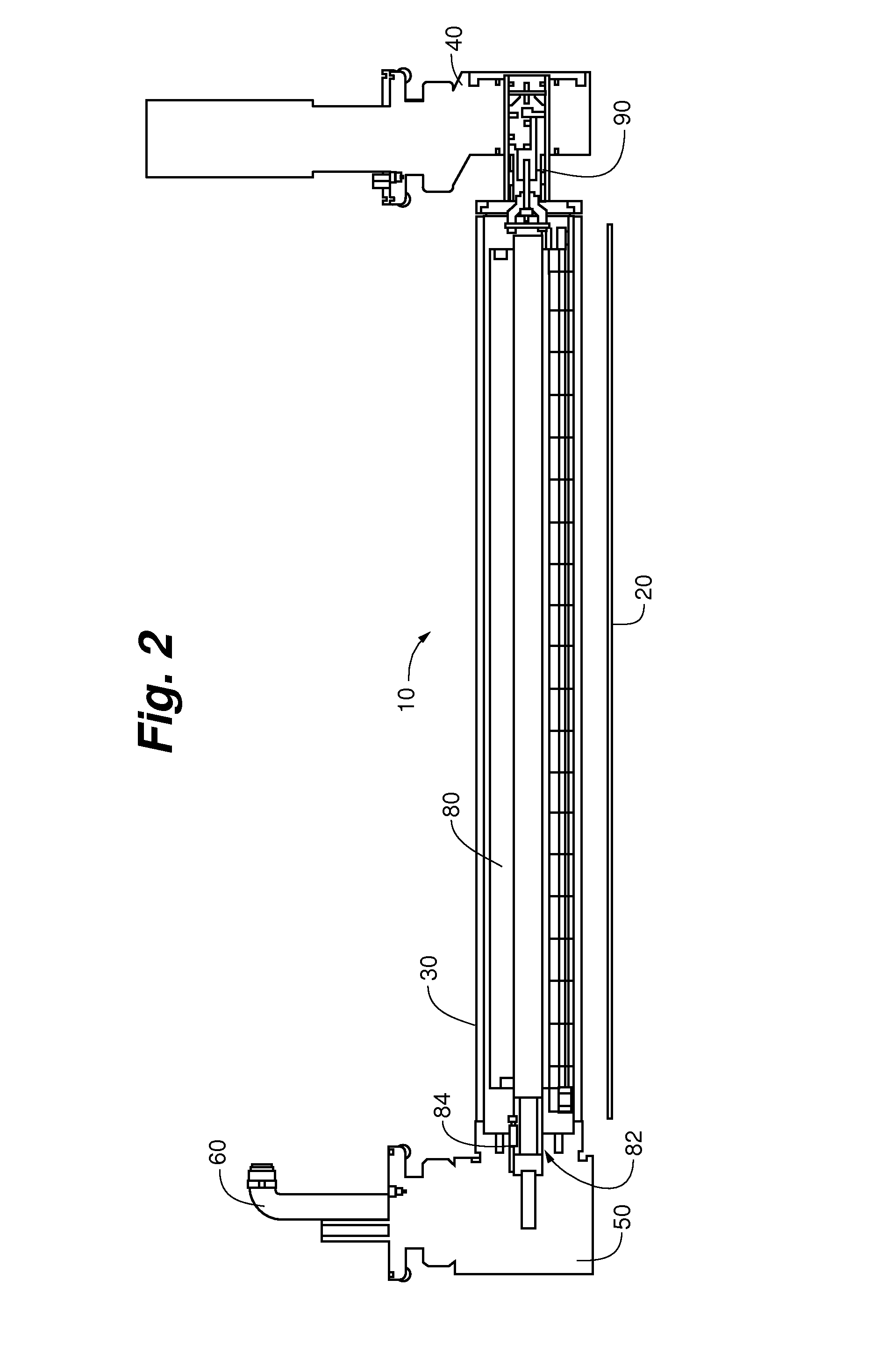
[0022]FIGS. 1 and 2 show a rotatable target assembly in accordance with an embodiment of the present invention. As shown in FIGS. 1 and 2, the target assembly 10 is useful for coating a substrate 20 with material from a cylindrical target 30 in a sputtering process. Cylindrical target 30 is rotatable about its longitudinal axis commonly by means of an electric motor or other motive device. In some embodiments, the rotating means comprises a drive end block 40 containing a motor useful for rotating cylindrical target 30. Target assembly 10 may be provide...


PUM

PropertyMeasurementUnit
distanceaaaaaaaaaa
longitudinal distanceaaaaaaaaaa
magnetic fieldaaaaaaaaaa

Abstract

In some embodiments, the invention includes a cylindrical cathode target assembly for use in sputtering target material onto a substrate that comprises a generally cylindrical target, means for rotating the target about its axis during a sputtering operation, an elongated magnet carried within the target for generation of a plasma-containing magnetic field exterior to but adjacent the target, a framework for supporting the magnet against rotation within the target, and a power train for causing the magnet to oscillate within and axially of the target in a substantially asynchronous manner to promote generally uniform target utilization along its length, as well as its method of use. In some embodiments, the magnet is oscillated in response to rotation of the target.

Description

CROSS REFERENCE TO RELATED APPLICATION[0001]The present application claims priority to provisional U.S. patent application filed Jul. 1, 2004 and assigned Ser. No. 60 / 584,535, the entire disclosure of which is incorporated herein by reference.FIELD OF THE INVENTION[0002]The present invention relates to cylindrical targets useful in magnetron sputtering.BACKGROUND OF THE INVENTION[0003]Magnetron sputtering of various materials onto substrates such as glass panes involves the use of a cathodic target, a magnet to produce a magnetic field adjacent to the target, and an inert gas such as argon which forms a plasma that is contained by the magnetic field. Targets can be of various configurations, but cylindrical targets that rotate about their axes during a sputtering operation are widely used. These targets are usually tubular, and employ a magnet that is positioned within the interior of the target. Although the target rotates about its axis, the magnet commonly does not; rather, the m...

Claims


Application Information

Patent Timeline
Patent Type & Authority Patents(United States)
IPC IPC(8): C23C14/00
CPCH01J37/3405H01J37/3423H01J37/3455H01J37/3497
Inventor HARTIG, KLAUSSMITH, STEVE E.MADOCKS, JOHN E.
Owner GENERAL PLASMA
Why Eureka
Try Eureka