
Circuit and method of temperature dependent power amplifier biasing

a power amplifier and temperature-dependent technology, applied in the field of power amplifiers, can solve the problems of changing the electromagnetic, electrical, and other physical characteristics of the pa, its constituent components, or its associated circuitry, and the temporal variance of the gain and phase response of the pa from what is required and expected is undesirable,

Active Publication Date: 2011-08-09
SIGE SEMICON
View PDF6 Cites 49 Cited by
  • Summary
  • Abstract
  • Description
  • Claims
  • Application Information

AI Technical Summary

Benefits of technology

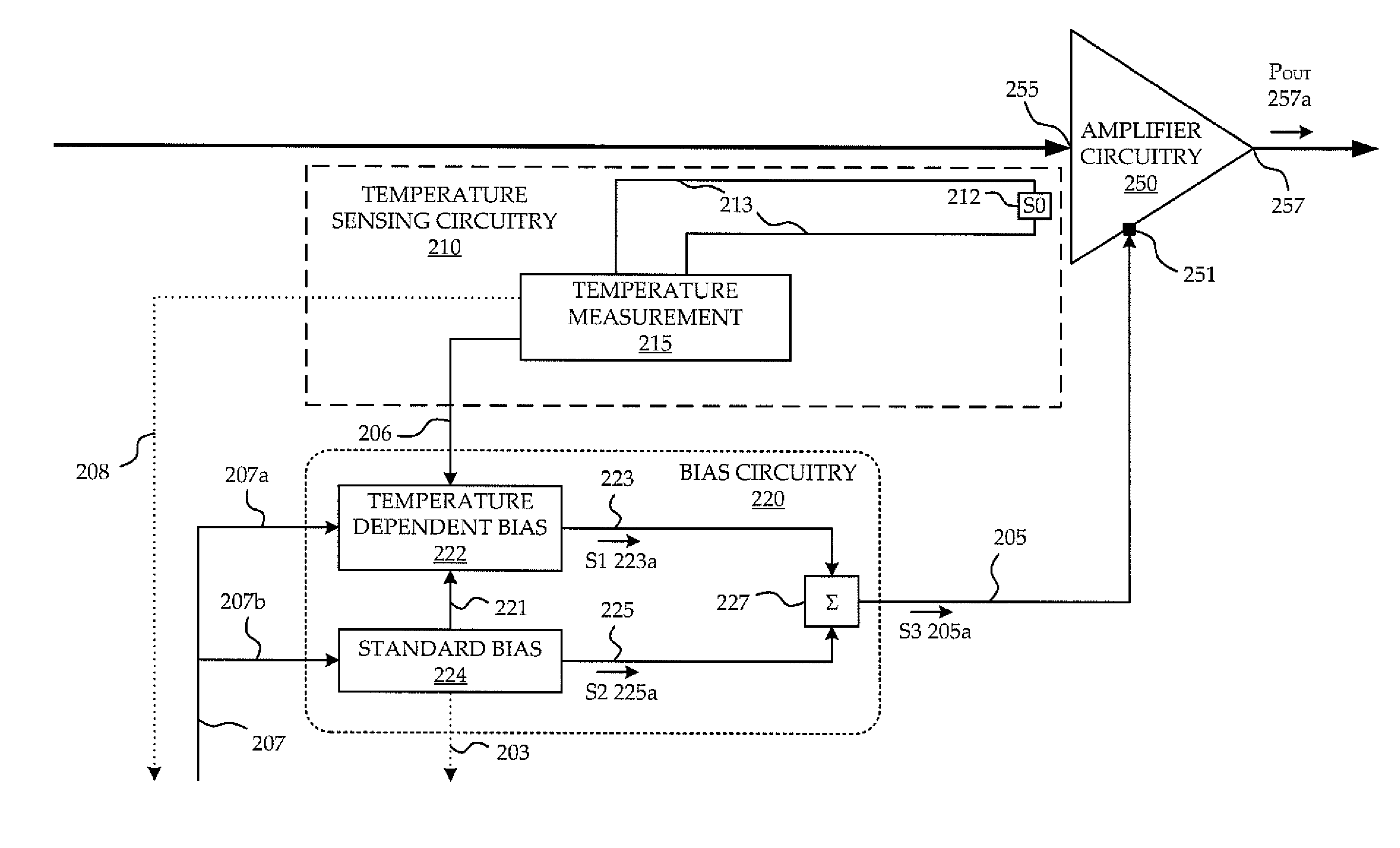
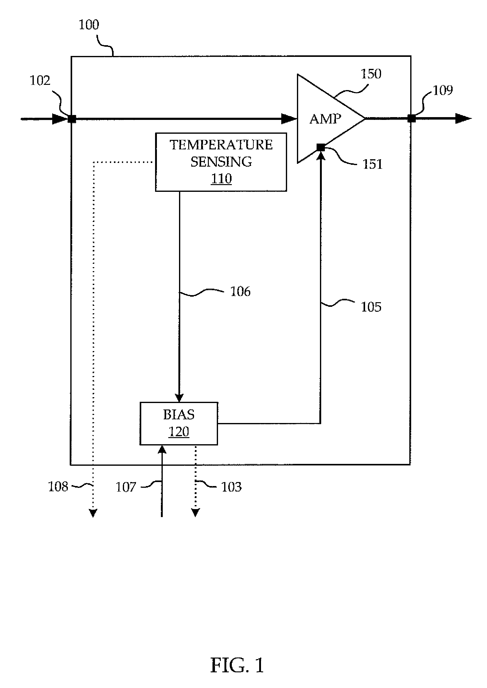
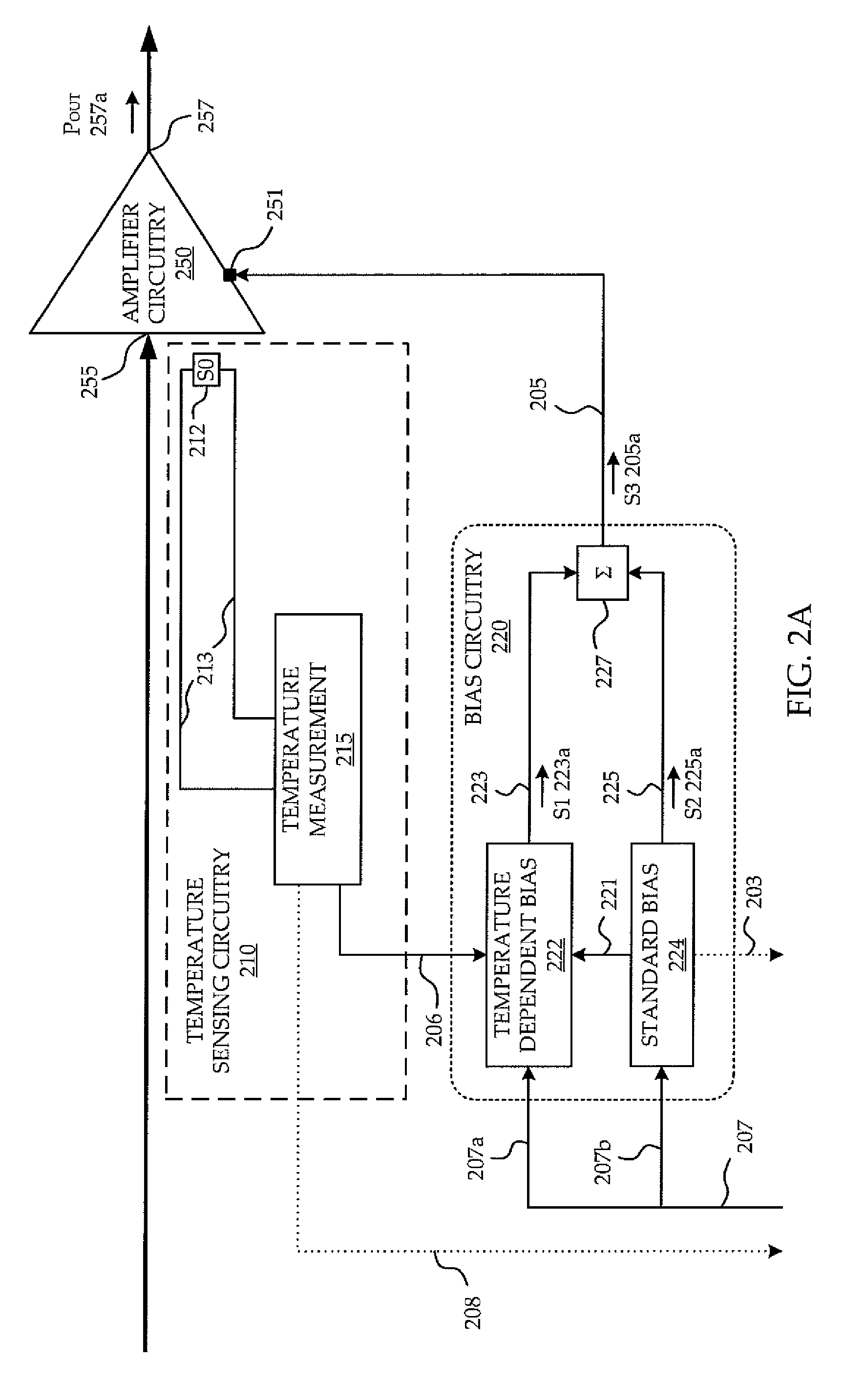
"The invention provides a method and circuit for biasing a power amplifier in a way that takes into account the temperature of the amplifier circuitry. This allows for a more accurate and precise biasing of the amplifier circuitry to a desired gain and phase. This can improve the performance and reliability of the power amplifier in RF communication systems."

Problems solved by technology

In most applications, a temporal variance of the gain and phase response of a PA from what is required and expected is undesirable.
A temporal variance in the gain or phase shift experienced by the input signal results in a temporal variance in both the magnitude and phase of the output signal.
Not surprisingly, changing operating conditions can lead to changing electromagnetic, electrical, and other physical characteristics of the PA, its constituent components, or its associated circuitry.
As such, changing the operating conditions or operating point of the PA can lead to changes in the gain or phase response of the PA.
This approach may not be acceptable in the context of various radio transmission standards such as IEEE 802.11.
Although the speed-up capacitor can improve the settling time of the PA, as a passive mechanism it cannot provide the additional forward current until the RF input signal itself arrives.
Consequently, the beginning of the RF signal data will suffer from some amount of dynamic EVM and the additional current may not be sufficient to bring the PA into a thermally settled state at a desired rate.
The external passive networks according to the known solutions possess various packaging and performance compromises.
Waiting for a PA and its associated circuitry to warm-up and become thermally settled before using it, although avoiding dynamic EVM, introduces undesirable delay.

Method used


Image

  • Circuit and method of temperature dependent power amplifier biasing
  • Circuit and method of temperature dependent power amplifier biasing
  • Circuit and method of temperature dependent power amplifier biasing

Examples


Embodiment Construction

[0019]The embodiments described below illustrate features of the invention in the context of an Integrated Chip (IC) power amplifier. It is to be understood that the invention applies to a power amplifier of any type, including among others, a power amplifier which is FET based, tube based, or any combination thereof, as long as the power amplifier utilizes biasing voltage or current signals to set the gain and phase response of its amplification, and would benefit from settling to minimize distortion due to changing gain and phase response during the arrival of the input signal.

[0020]The invention described herein below mitigates the aforementioned drawbacks of known systems by limiting the need for external components, improving dynamic EVM performance of PAs, reducing fine tuning and optimization in the prototype phase, and permitting use of the PA to amplify RF signals passing therethrough without undesirable delays.

[0021]Although various fluctuations in physical characteristics...


PUM


Abstract

A circuit and method are provided for reducing dynamic EVM of a power amplifier (PA) used for RF communication. A temperature dependent boost bias signal is applied to the bias input port of amplifier circuitry of the PA in dependence upon a temperature of the amplifier circuitry to compensate for transience in the gain or phase response of the PA while components of the PA is differentially warming-up, advantageously taking into account an actual temperature of the amplifier circuitry.

Description

FIELD OF THE INVENTION[0001]The invention relates to power amplifiers (PA), and more particularly to reduction of gain and phase variance of a PA and hence reduction of dynamic error vector magnitude of amplified signals.BACKGROUND OF THE INVENTION[0002]One consideration for the performance of a power amplifier is its ability to exhibit the gain and phase response which is requested and / or expected of it. In most applications, a temporal variance of the gain and phase response of a PA from what is required and expected is undesirable. An input signal to the PA experiences amplification in accordance with the expected gain and the phase of the signal may be shifted. A temporal variance in the gain or phase shift experienced by the input signal results in a temporal variance in both the magnitude and phase of the output signal.[0003]In a PA used in an RF transmitter or transceiver for RF communication, one measure of the error in the gain and phase response exhibited by a PA is what i...

Claims


Application Information

Patent Timeline
Patent Type & Authority Patents(United States)
IPC IPC(8): H03F3/04
CPCH03F1/30H03F3/19H03F3/211H03F2200/447H03F2200/468
Inventor PUKHOVSKI, ANATOLI
Owner SIGE SEMICON
Learn More