Hologram optical element, fabrication method thereof, and image display apparatus

a technology of optical elements and fabrication methods, applied in the field of hologram optical elements, image display apparatuses, can solve the problems of color unevenness in the viewing angle that is more likely, and achieve the effect of improving usability

Inactive Publication Date: 2011-08-16
KONICA MINOLTA INC
View PDF6 Cites 80 Cited by
  • Summary
  • Abstract
  • Description
  • Claims
  • Application Information

AI Technical Summary

Benefits of technology

[0013]The present invention has been made under the background described above, and it is an object of the invention to provide an image display apparatus that affords enhanced usability by offering different viewing characteristics in different directions simultaneously, to provide a hologram optical element employed in such an image display apparatus, and to provide a method of fabricating such a hologram optical element.
[0018]According to the invention, it is possible to realize different viewing characteristics in different directions simultaneously, and thus it is possible to realize an image display apparatus that affords enhanced usability.

Problems solved by technology

When a display device with a laterally elongate screen like these is applied to an image display apparatus, at the position of the optical pupil, the viewer is allowed a laterally expanded viewing angle, and this makes color unevenness within the viewing angle more likely.

Method used


Image

  • Hologram optical element, fabrication method thereof, and image display apparatus
  • Hologram optical element, fabrication method thereof, and image display apparatus
  • Hologram optical element, fabrication method thereof, and image display apparatus

Examples


embodiment 1

[0035]An embodiment of the invention will be described below with reference to the relevant drawings.

1. Construction of an HMD

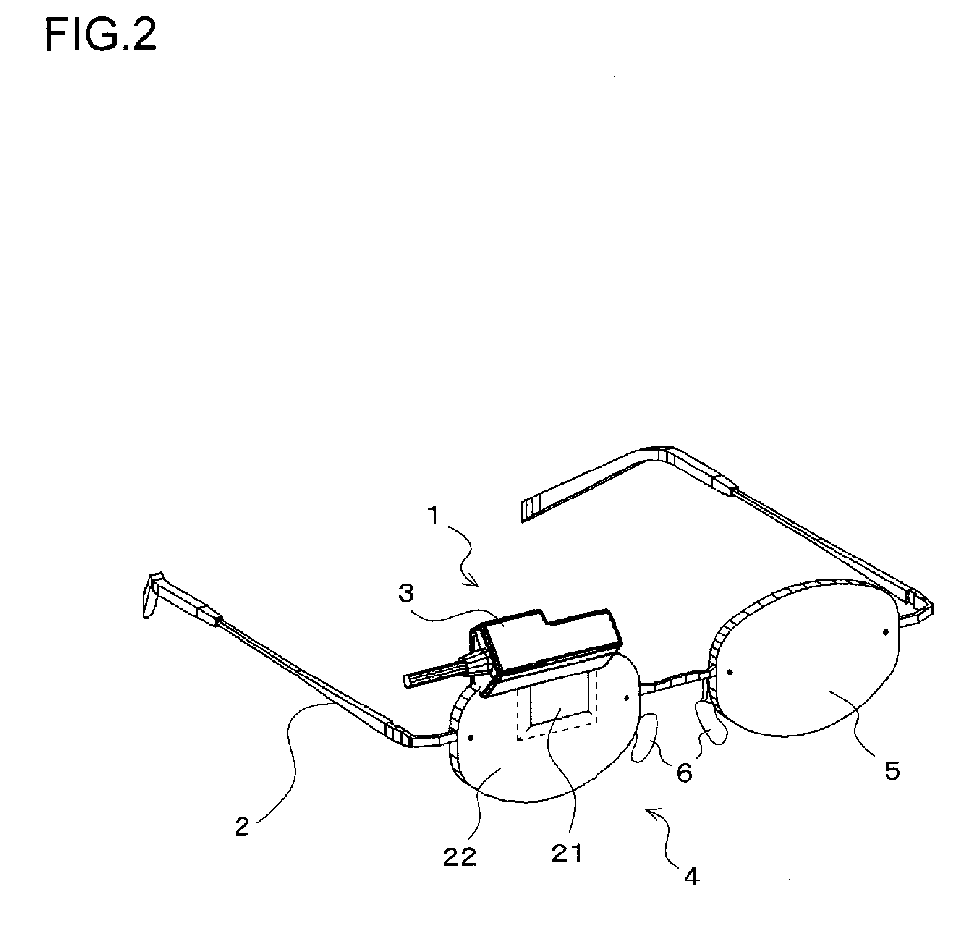
[0036]FIG. 2 is a perspective view showing an outline of the construction of an HMD according to this embodiment. The HMD is composed of an image display apparatus 1 and a supporting member 2 (first supporting member).

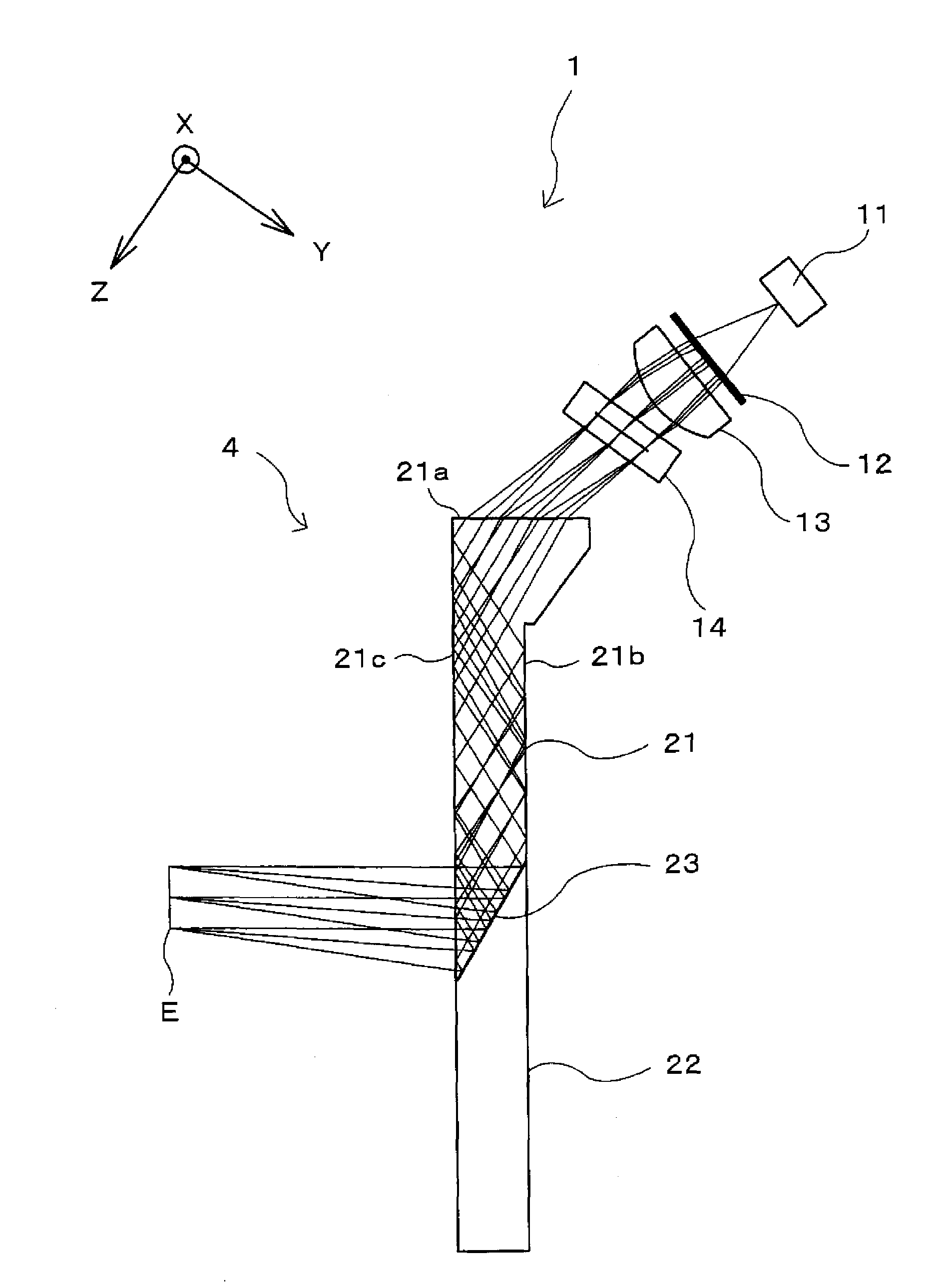
[0037]The image display apparatus 1 has a casing 3 that houses at least a light source 11 and a display device 14 (for both, see FIG. 3). The casing 3 holds part of an eyepiece optical system 4. The eyepiece optical system 4 is composed of an eyepiece prism 21 and a deflector prism 22—of which both will be described later—bonded together, and is as a whole shaped like one of the lenses of eyeglasses (in FIG. 2, the one for the right eye). The image display apparatus 1 also has a circuit board (unillustrated) that supplies the light source 11 and the display device 14 with at least driving electric power and an image signal by way of a cable (uni...

embodiment 2

[0098]Another embodiment of the invention will be described below with reference to the relevant drawings. For the sake of convenience, in the following description, such parts as are found also in Embodiment 1 are identified with common reference signs, and their description will not be repeated.

[0099]FIG. 9 is an illustrative diagram showing in detail the construction of the fabrication optical system 50 used in this embodiment in a form clearly showing, in particular, the optical path on the YZ-plane and the optical path on the ZX-plane. In this embodiment, in the optical system on the reference-light side of the fabrication optical system 50 for the exposure of the hologram photosensitive material 23a for the fabrication of the hologram optical element 23, the cylindrical lens 71 is omitted while the cylindrical lens 72 is retained. In other respects, Embodiment 2 is the same as Embodiment 1.

[0100]The cylindrical lens 72 focuses incident light (here, the light incident via the m...

embodiment 3

[0103]Yet another embodiment of the invention will be described below with reference to the relevant drawings. For the sake of convenience, in the following description, such parts as are found also in Embodiment 1 or 2 are identified with common reference signs, and their description will not be repeated.

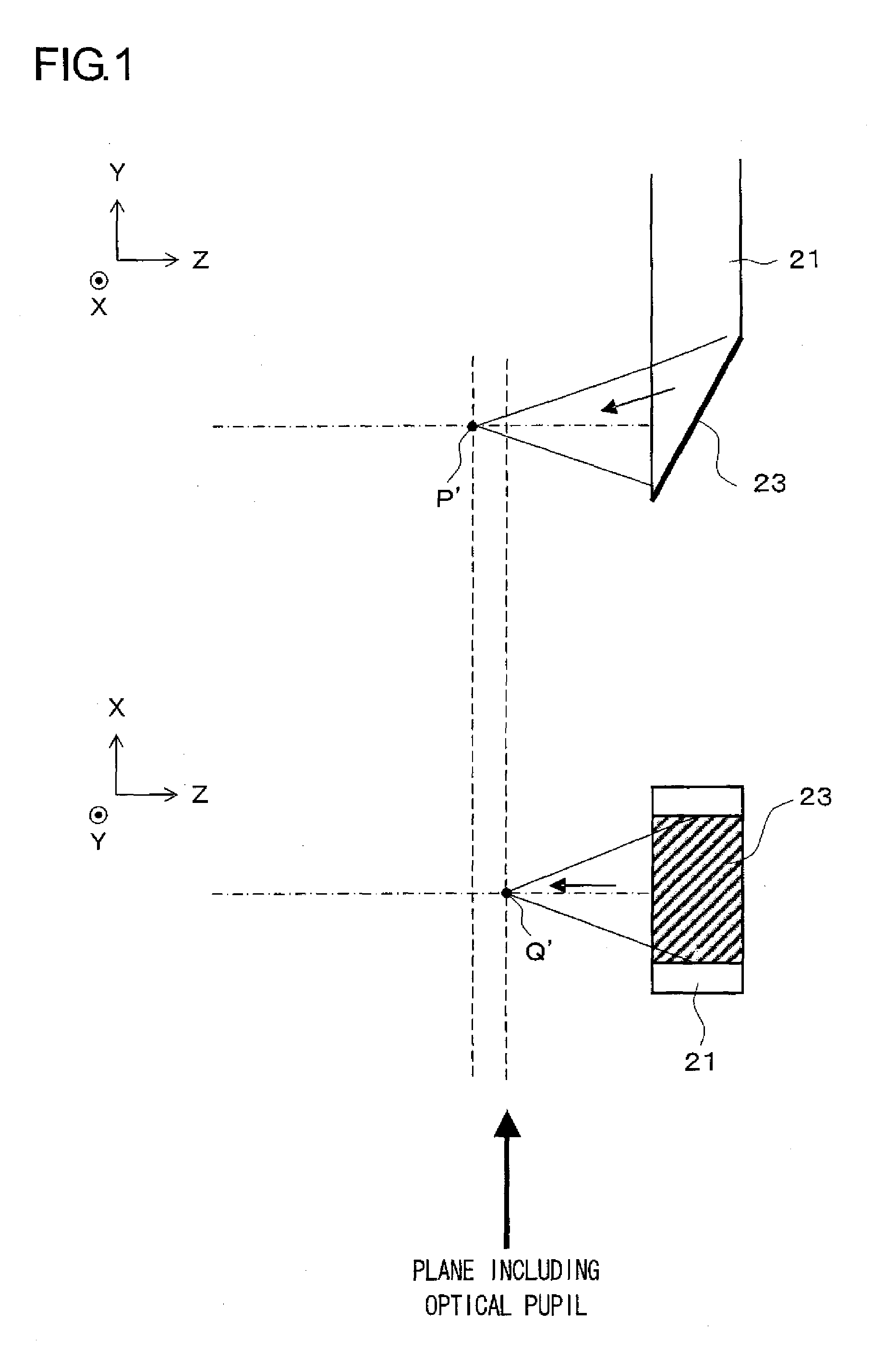
[0104]FIG. 10 is an illustrative diagram showing in detail the construction of the fabrication optical system 50 used in this embodiment in a form clearly showing, in particular, the optical path on the YZ-plane and the optical path on the ZX-plane. In this embodiment, in the optical system on the reference-light side of the fabrication optical system 50 for the exposure of the hologram photosensitive material 23a for the fabrication of the hologram optical element 23, the arrangement of the cylindrical lenses 71 and 72 is reversed; as a result, the focus position (the focus point P) on the YZ-plane at the time of exposure is substantially coincident with the optical pupil at the t...


PUM


Abstract

A volume-phase reflection hologram optical element is fabricated by exposing a hologram photosensitive material to two coherent light beams. One exposure light beam has an axis-asymmetric wavefront, and the other exposure light beam has focus points different in the optical axis direction (Z-direction) between on a plane (ZX-plane) including one of two directions (X- and Y-directions) mutually perpendicular on a sectional plane perpendicular to that light beam and on a plane (YZ-plane) including the other of those two directions. Thus, an image display apparatus is realized in which at the time of reproduction, the component of a predetermined wavelength of the image light diffraction-reflected by the hologram optical element is focused at positions different in the optical axis direction between on the ZX-plane and on the YZ-plane, offering different image viewing characteristics between in the X- and Y-directions.

Description

[0001]This application is based on Japanese Patent Application No. 2007-144643 filed on May 31, 2007, the contents of which are hereby incorporated by reference.BACKGROUND OF THE INVENTION[0002]1. Field of the Invention[0003]The present invention relates to a hologram optical element fabricated by exposing a hologram photosensitive material to two coherent light beams, to a method of fabricating such a hologram optical element, and to an image display apparatus employing such a hologram optical element.[0004]2. Description of Related Art[0005]Conventionally, there have been proposed various image display apparatuses employing a hologram optical element (hereinafter also referred to as “HOE”). FIG. 14 is an illustrative diagram showing such an image display apparatus in a form with its optical path straightened. In this image display apparatus, the light from a light source 101 is converted into a parallel beam by an illumination lens 102, is then diffused by a diffuser plate 103, th...

Claims


Application Information

Patent Timeline
Patent Type & Authority Patents(United States)
IPC IPC(8): G03H1/00G02B5/32G09G5/00
CPCG02B5/32G02B27/0103G02B27/1073G02B27/1086G03H1/04G02B2027/0109G02B2027/0123G03H2001/0439G03H2001/2231G03H2222/55
Inventor ENDO, TAKESHISHIMIZU, YOSHIE
Owner KONICA MINOLTA INC
Why Eureka
Try Eureka