Tubular memory module

a memory module and tubular technology, applied in the field of memory modules, can solve problems such as significant design challenges

Active Publication Date: 2011-08-16
LENOVO GLOBAL TECH INT LTD
View PDF15 Cites 11 Cited by
  • Summary
  • Abstract
  • Description
  • Claims
  • Application Information

AI Technical Summary

Problems solved by technology

In space-constrained computer systems, there are significant design challenges in fitting all of the desired features and functions for a product within a given form factor.
These challenges are present in the design of most computer systems, and particularly in compact systems such as blade servers.
For example, increasing the capacity and performance of memory of a blade server is accompanied by the associated challenges of fitting the memory within a compact blade server housing and sufficiently cooling the memory.

Method used


Image

  • Tubular memory module
  • Tubular memory module
  • Tubular memory module

Examples


Embodiment Construction

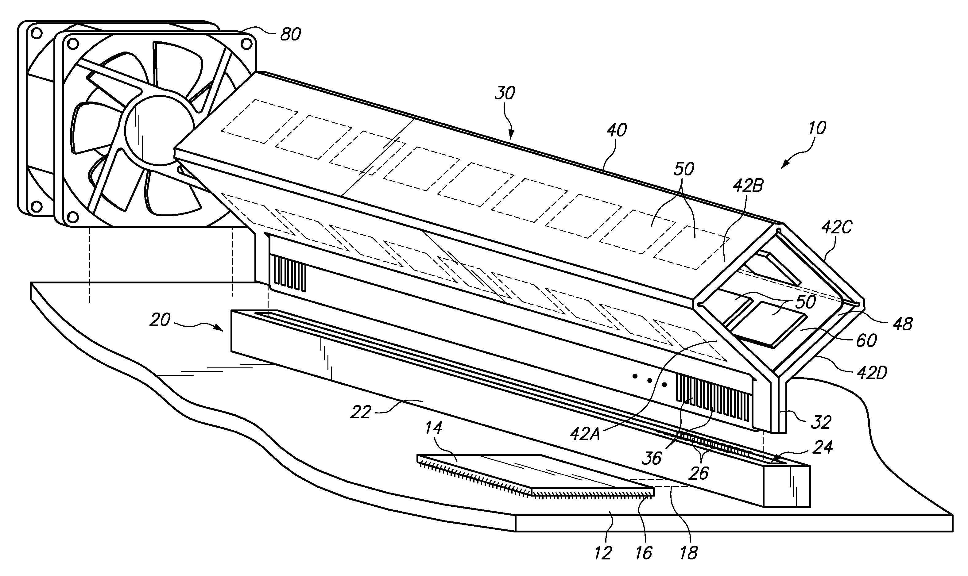
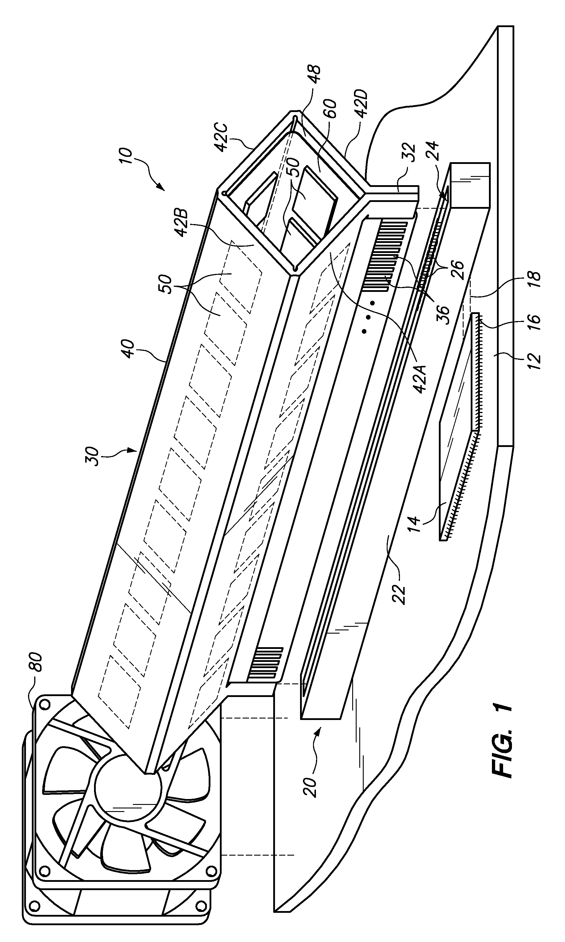
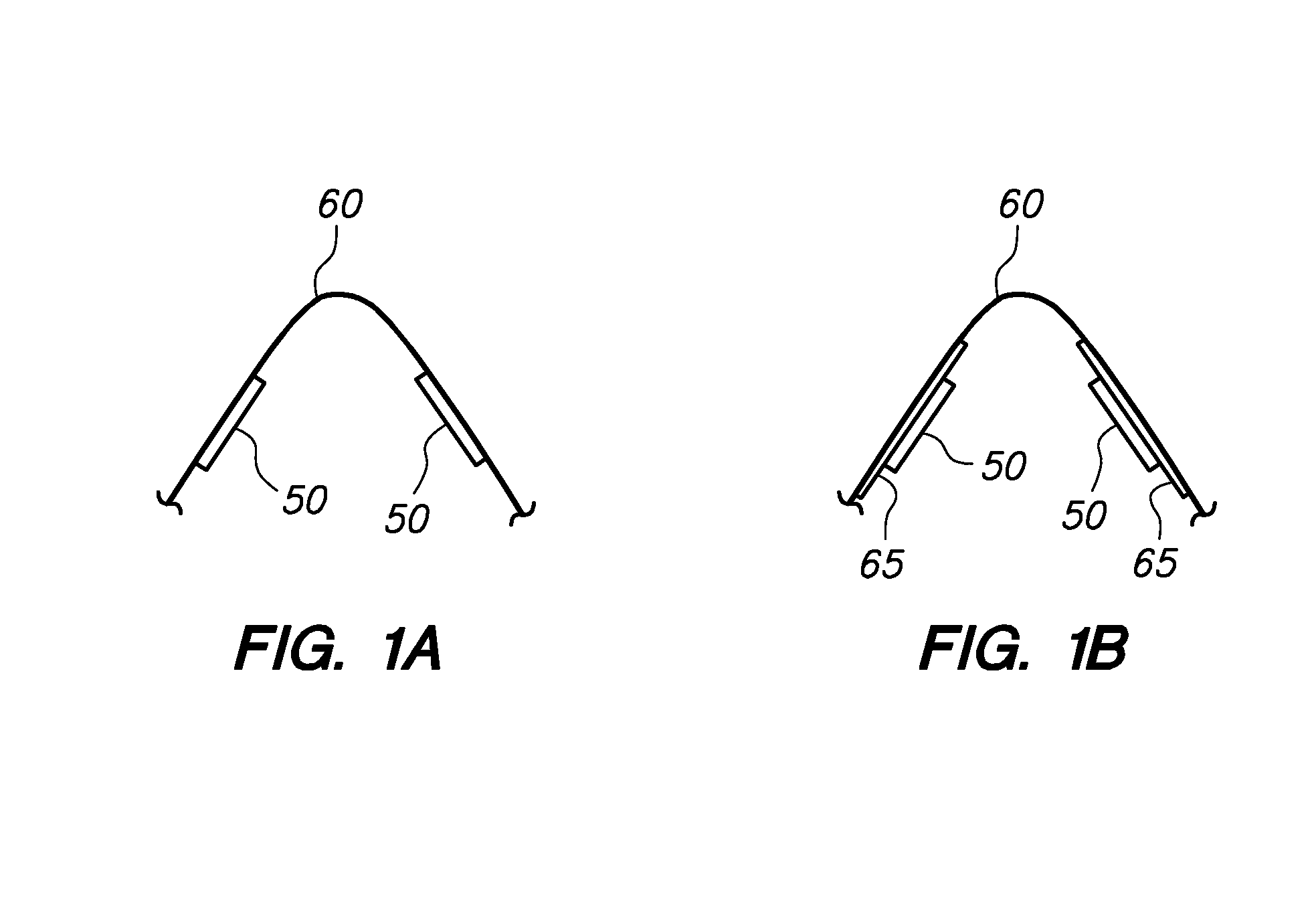
[0021]Embodiments of the invention presented below include various configurations of a tubular memory module and methods of forming a tubular memory module. For example, in at least one embodiment, a memory module has a tubular frame with nine panels coupled at the edges to form a square tubular cross-section. A card edge extends along the tubular frame. A flexible circuit having a plurality of “DRAM” memory chips is secured to the tubular frame, with a plurality of electrical terminals positioned along the card edge. Each panel of the tubular frame supports at least one row of memory packages, with each memory package having one or more “DRAM” memory chips. The memory module may be connected to a memory module connector on a circuit board, such that the electrical terminals positioned along the card edge electrically contact corresponding electrical terminals in the memory module connector. A memory controller on the circuit board may then read and write to the memory module.

[0022]...


PUM

PropertyMeasurementUnit
flexibleaaaaaaaaaa
poweraaaaaaaaaa
pressure dropaaaaaaaaaa

Abstract

Memory systems and methods of forming memory modules. In one embodiment, a computer memory system includes a substantially tubular frame with an elongate card edge extending along the frame. A flexible circuit comprising a flexible substrate, a plurality of memory chips affixed to the flexible substrate, and a plurality of electrical terminals interconnected with the memory chips, is secured along a perimeter of the tubular frame with the electrical terminals arranged along the card edge.

Description

BACKGROUND OF THE INVENTION[0001]1. Field of the Invention[0002]The present invention relates to computer system memory, and more specifically to memory modules.[0003]2. Background of the Related Art[0004]In space-constrained computer systems, there are significant design challenges in fitting all of the desired features and functions for a product within a given form factor. These challenges are present in the design of most computer systems, and particularly in compact systems such as blade servers. Blade servers provide a robust set of features and performance capabilities within the space constraints of industry-standard module dimensions. Blade servers and subsystems must also address thermal and power demands so that the subsystems may operate at increasing performance levels. For example, increasing the capacity and performance of memory of a blade server is accompanied by the associated challenges of fitting the memory within a compact blade server housing and sufficiently c...

Claims


Application Information

Patent Timeline
Patent Type & Authority Patents(United States)
IPC IPC(8): H05K1/00
CPCG06F1/20H05K1/189H05K1/117H05K3/0061Y10T29/49002H05K2201/056H05K2201/09745H05K2201/10159H05K2203/302H05K2201/047
Inventor HINKLE, JONATHAN RANDALL
Owner LENOVO GLOBAL TECH INT LTD
Why Eureka
Try Eureka