Apparatus for splicing webs

a technology of splicing webs and splicing devices, applied in the direction of photosensitive materials, mechanical control devices, instruments, etc., can solve the problems of expensive drive systems and controls for flying splicers, and achieve the effect of reducing wear on both the anvil strip and the cutting blad

Active Publication Date: 2011-08-23
TAMARACK PRODS
View PDF13 Cites 15 Cited by
  • Summary
  • Abstract
  • Description
  • Claims
  • Application Information

AI Technical Summary

Benefits of technology

[0007]The invention includes a splicer that makes running splices as opposed to zero-speed splices and, further, does so with minimal effect on web tension. The splicer makes rapid splices thereby consuming a relatively small amount of web from an accumulator. The splicer can be manually, crank-operated or can be equipped for automatic operation. The splicer provides a lap or butt splicer that simultaneously cuts the expiring web while joining the prepared (i.e., pre-taped leading edge), replenishing web. The instant splicer includes a simplified mechanism compared to prior art splicers. It eliminates clamping bars and the complications of prior art sequencing clamping bars with cutting and other operations. Further, the instant splicer is compatible with either two-sided or single-side adhesive splicing tapes, and it uses rotary cutting rather than reciprocating, transverse cutting wheels / blades or shear cutting blades / anvils. The instant splicer uses inexpensive cutting blades, and the blades which are easy to replace.
[0013]Drives an anvil strip between the depleting web and replenishing web via a simple crank / slider mechanism. The anvil strip provides two functions: one side acts as an anvil surface for cutting the depleting web against, the other side acts as a shield to prevent cutting the replenishing web
[0018]In the instant invention, the anvil strip is only interposed between the cylinders when a cut is being effected. And the anvil strip is used in a unique way: One side of the anvil strip serves as a cutting anvil surface for cutting one web. The other side of the anvil strip simultaneously and advantageously protects a second web from being cut.
[0019]The reciprocating anvil strip both moves the anvil strip clear of the web while web is consumed by the host machine, and approximately matches the anvil strip velocity with the cutting blade velocity. This reduces wear on both the anvil strip and cutting blade.
[0020]The instant invention provides an elegantly simple method of making a ‘flying splice’ by providing a small amount of ‘stored’ web to assure that the replenishing web is readily accelerated to approximately the speed of the expiring web and that the leading end of the replenishing web is joined in close proximity to the cut tail end of the expiring web. This eliminates the need for sophisticated controls and drives for matching the speed of the webs during the splice. The instant invention simply has a small amount of slack web without the guiding and controlling mechanism of some prior art devices.

Problems solved by technology

These “flying” splicers require costly drive systems and controls.

Method used


Image

  • Apparatus for splicing webs
  • Apparatus for splicing webs
  • Apparatus for splicing webs

Examples


Embodiment Construction

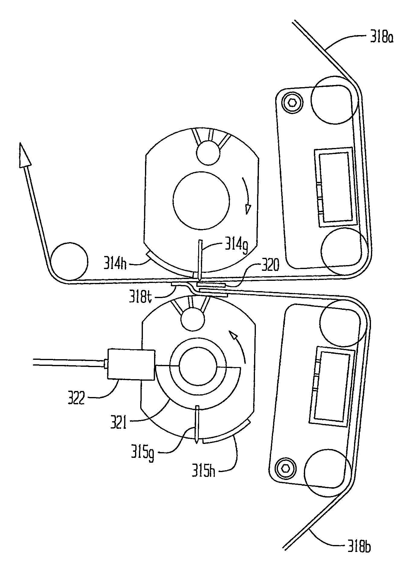
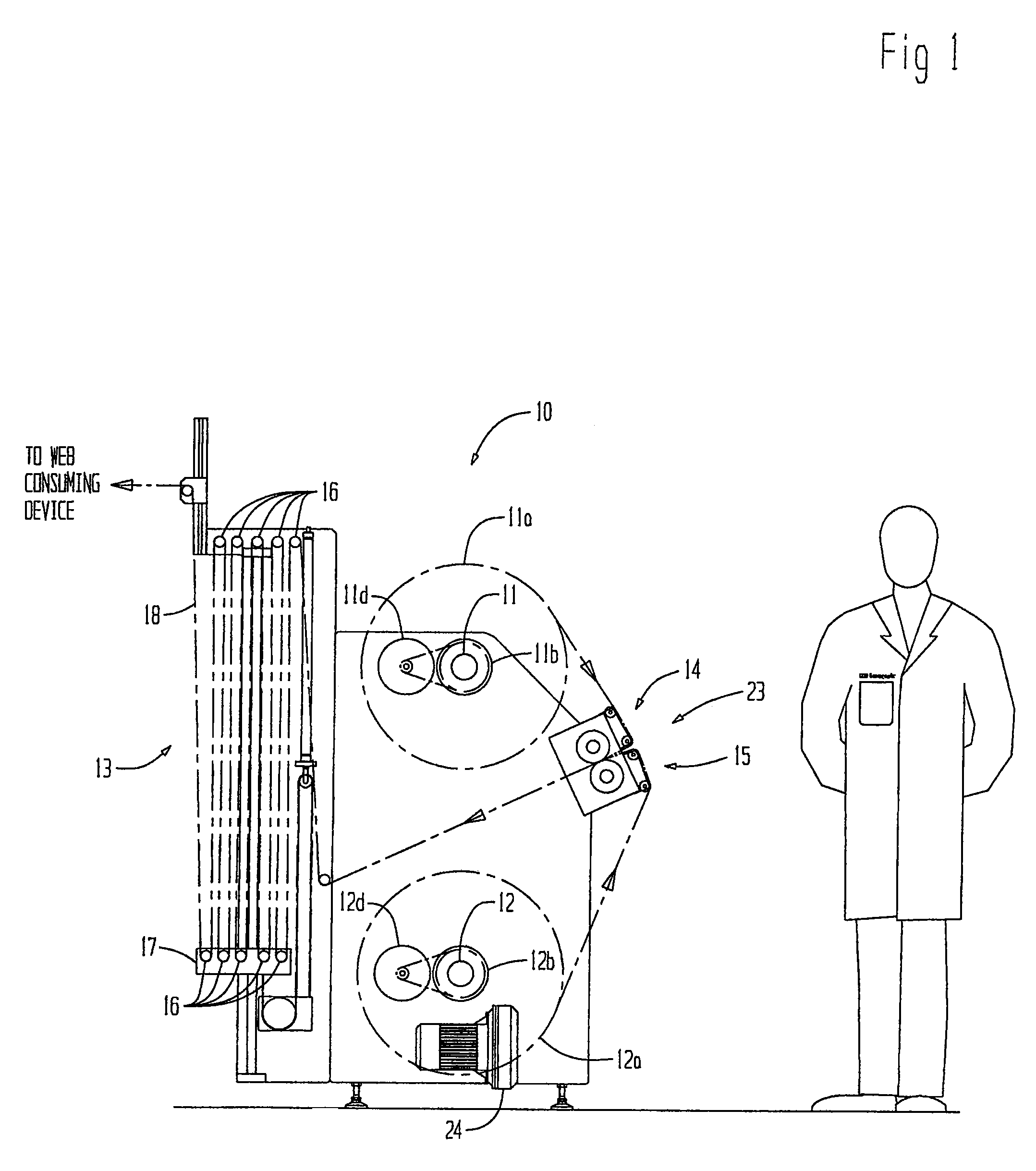
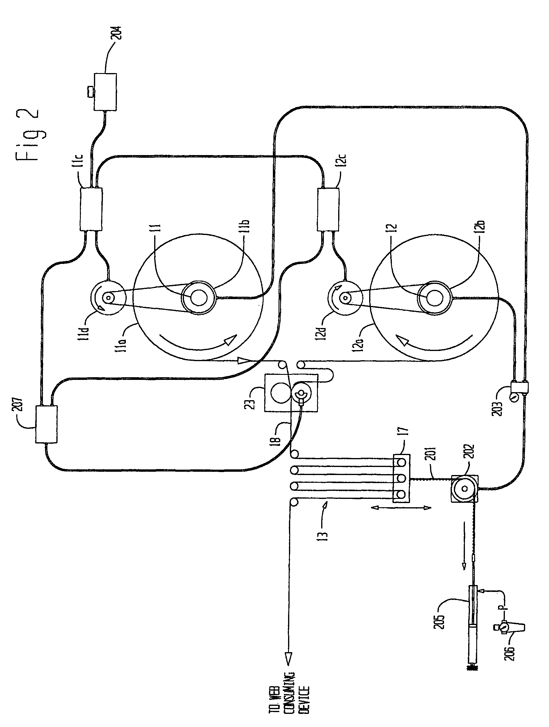
[0028]A web unwinding and splicer apparatus 10, shown in FIG. 1 illustrates a general configuration, including roll unwind spindles 11 and 12, and accumulator 13 supported by conventional frame work. The apparatus 10 also includes mirror-image splicing heads 14 and 15 as part of a splicing apparatus 23. The splicing heads 14 and 15 are configured to provide a novel and inventive rolling splicing process, as will be disclosed herein.

[0029]In operation, one of the spindles 11 or 12 is supplying web 18 to the accumulator 13 and in turn, supplies the web 18 to whatever web consuming machinery the apparatus 10 is connected to, such as a Vista® window applicating machine manufactured by Tamarack Products Inc. of Wauconda, Ill. For example, spindle 11 is supplying web 18 from a roll of web material 11a and roll 11a will eventually be depleted. Splicing head 15 is prepared with the lead end of a replenishing roll 12a on spindle 12. When roll 11a is nearly depleted, the splicing mechanism 23...


PUM

PropertyMeasurementUnit
thicknessaaaaaaaaaa
thicknessesaaaaaaaaaa
displacementaaaaaaaaaa

Abstract

A continuous splicer includes first and second closely spaced rotating cylinders each having a respective cutting element and tape retaining arrangement disposed on its outer periphery. With a depleting web fed by the first cylinder and a replenishing web fed by the second cylinder, an end of the replenishing web is adhesively joined to the depleting web while in motion and the depleting web is severed by the first cylinder's cutting element in forming a splice of the two webs. As the replenishing web depletes, a third web may be inserted on the first cylinder and automatically or manually spliced to the original replenishing web without stopping or re-configuring the splicer. The splicer is capable of delivering the webs at a constant rate or a rapidly changing and / or dynamic cycling rate, and applies relatively low web tension for operation with delicate, narrow and extensible webs.

Description

RELATED APPLICATION[0001]This application claims the benefit of U.S. Provisional Application No. 61 / 147,563 filed Jan. 27, 2009 for “APPARATUS FOR SPLICING WEBS”.FIELD OF THE INVENTION[0002]The present invention provides an improved splicing apparatus and method, suitable for handling a wide range of materials, web widths, and web thicknesses. It is particularly suitable for handling relatively delicate webs of paper or poly film material.BACKGROUND OF THE INVENTION[0003]Summary of prior art splicers: Many of the prior art unwinding (i.e., supplying rather than rewinding) splicers are zero-speed splicers, that is the depleting web is stopped and joined to a prepared, stationary replenishing web. The supply of web to a web consuming device may continue uninterrupted as web is taken from a stored supply of web in a festoon or accumulator. Most of these zero-speed splicers use a cutter that cuts the web with a transverse motion, in a reciprocating cycle.[0004]There are also “flying” sp...

Claims


Application Information

Patent Timeline
Patent Type & Authority Patents(United States)
IPC IPC(8): B65H21/00
CPCB65H19/1836B65H19/20B65H2301/46172B65H2301/462B65H2301/4631B65H2301/4641B65H2406/341
Inventor MACHAMER, DAVID E.
Owner TAMARACK PRODS
Why Eureka
Try Eureka