Differential apparatus for vehicle

a technology for differential cases and vehicles, applied in mechanical devices, transportation and packaging, gears, etc., can solve the problems of large viscosity resistance of hypoid gears, high price of tapered roller bearings, and large tooth surface load and sliding velocity of hypoid gears, so as to reduce the diameter of the axial periphery and the diameter of the differential case in the diametrical direction

Inactive Publication Date: 2011-08-30
SUBARU CORP
View PDF8 Cites 11 Cited by
  • Summary
  • Abstract
  • Description
  • Claims
  • Application Information

AI Technical Summary

Benefits of technology

[0015]According to the inventions, engine power transmitted by the input shaft is input from the crown gear of the orthogonal axis gear into the sun gear of the adjacent planetary gear reduction mechanism portion. The engine power is also input from the planetary carrier of the planetary gear reduction mechanism portion into the ring gear of the adjacent differential gear mechanism portion, which employs a planetary gear mechanism, and output from the planetary carrier and the sun gear of the differential gear mechanism portion to the left and right output shafts, respectively. Thus, power transmission from the input shaft to the planetary gear reduction mechanism portion, which is conventionally performed in a vertical direction, i.e. an orthogonal direction to (the diametrical direction of) the left and right output shafts, is shifted to a horizontal direction, i.e. an identical direction to the axial center direction of the left and right output shafts, and therefore the need for a conventional housing disposed on the axial periphery of the left and right output shafts can be eliminated, enabling a diametrical direction reduction in the diameter of the differential case.
[0016]Further, by employing a double pinion type planetary gear mechanism in the differential gear mechanism portion, the differential apparatus can be made more compact while obtaining an appropriate speed reduction ratio for a typical vehicle.
[0017]According to the differential apparatus of the present invention, the orthogonal axis gear, planetary gear reduction mechanism portion, and differential gear mechanism are arranged along the axial center direction of the left and right output shafts, and therefore a conventional housing is not required, enabling a reduction in the diameter of the axial periphery of the left and right output shafts. As a result, the differential apparatus can be made more compact than a conventional apparatus.

Problems solved by technology

However, a tapered roller bearing is more expensive than a ball bearing and exhibits greater rolling resistance.
Further, the tooth surface load and sliding velocity of the hypoid gear are large, and therefore sufficiently viscous lubricating oil must be used.
However, the viscous resistance of such lubricating oil is great.
Hence, a hypoid gear may cause deterioration of the fuel economy, thereby affecting the fuel economy of a vertically installed engine vehicle or a four-wheel drive vehicle comprising the hypoid gear.
Hence, in both the former and the latter, the axial periphery of the left and right output shafts increases in diameter, leading to an increase in the size of the differential case.

Method used


Image

  • Differential apparatus for vehicle
  • Differential apparatus for vehicle
  • Differential apparatus for vehicle

Examples


Embodiment Construction

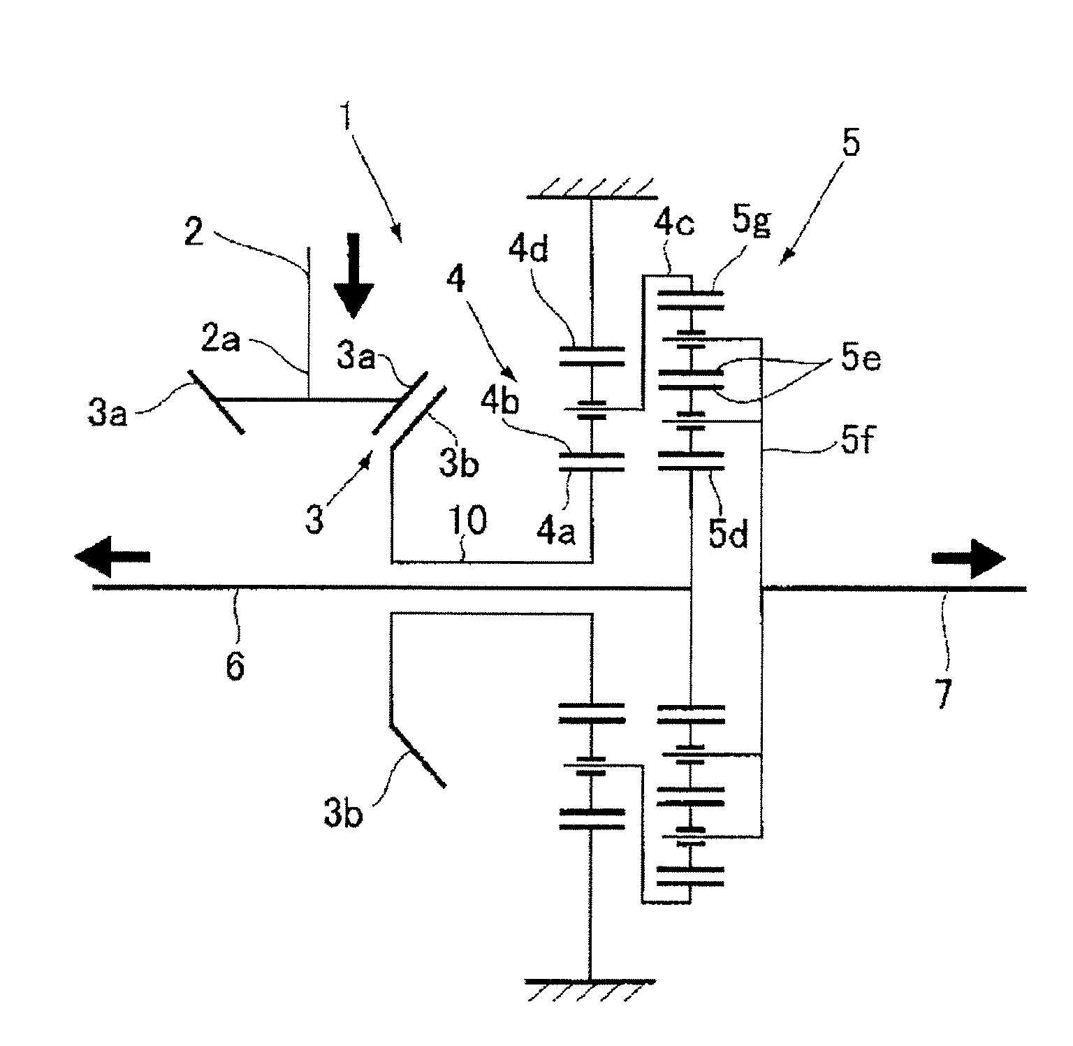
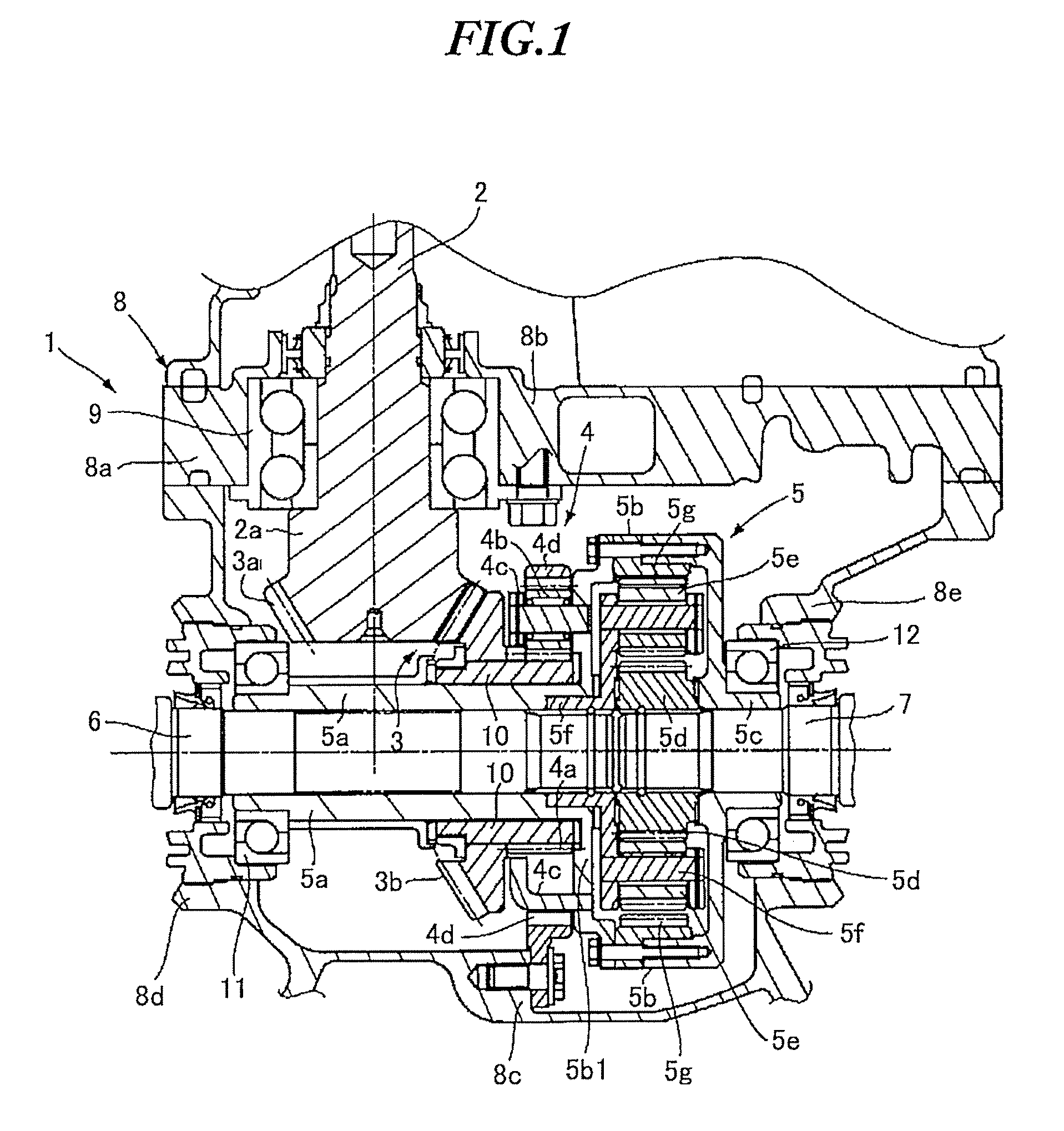
[0024]A differential apparatus according to an embodiment of the present invention will be described in detail below with reference to FIG. 1. FIG. 1 is a sectional plan view of the differential apparatus.

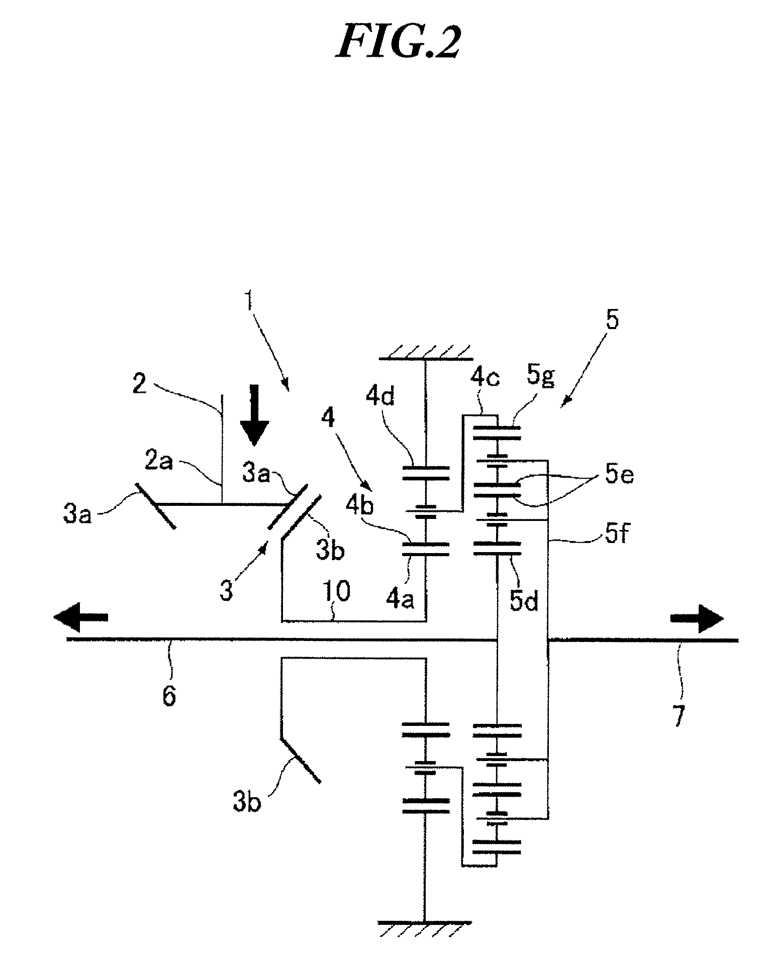
[0025]As shown in FIG. 1, a differential apparatus 1 is applied to a transaxle or rear differential for a vertically installed engine, and is constituted by an input shaft 2, a bevel gear 3 (for example, a straight bevel gear or a curved bevel gear) serving as an orthogonal axis gear, a planetary gear reduction mechanism portion 4, a differential gear mechanism portion (to be referred to hereafter as a planetary gear differential mechanism portion) 5 employing a planetary gear mechanism, and left and right output shafts 6, 7 for transmitting engine power transmitted from a speed change mechanism or a transfer mechanism to left and right drive wheels.

[0026]In more detail, the input shaft 2 is a power transmission shaft that extends in a front-rear direction, an output side (bevel ge...


PUM


Abstract

An orthogonal axis gear, a planetary gear reduction mechanism portion, and a differential gear mechanism portion are arranged along an axial center direction of left and right output shafts. The planetary gear reduction mechanism portion is constituted such that a sun gear thereof is provided as a continuation of a crown gear of the orthogonal axis gear, a ring gear thereof is fixed to a differential case, and a planetary carrier thereof serves as an output. Further, the differential gear mechanism portion employs a planetary gear mechanism and is constituted such that a ring gear of the planetary gear mechanism is provided as a continuation of the planetary carrier of the planetary gear reduction mechanism portion, a planetary carrier thereof is provided as a continuation of the left side output shaft, and a sun gear thereof is provided as a continuation of the right side output shaft.

Description

CROSS-REFERENCE TO RELATED APPLICATIONS[0001]The disclosure of Japanese Patent Application No. 2007-128788, filed on May 15, 2007 including the specification, drawings and abstract, is incorporated herein by reference in its entirety.BACKGROUND OF THE INVENTION[0002]1. Field of the Invention[0003]The present invention relates to a differential apparatus for a vehicle, and more particularly to a differential apparatus comprising an orthogonal axis gear that transmits the power of a front-rear extending input shaft to left and right output shafts.[0004]2. Description of the Related Art[0005]An apparatus disclosed in Japanese Unexamined Patent Application Publication 2004-278762 is known as a conventional differential apparatus comprising a hypoid gear, which is used widely as an orthogonal axis gear for a vehicle.[0006]As shown in FIGS. 3 and 4 (FIGS. 1 and 2 of Japanese Unexamined Patent Application Publication 2004-278762), in this differential apparatus (11), the rotation direction...

Claims


Application Information

Patent Timeline
Patent Type & Authority Patents(United States)
IPC IPC(8): F16H48/06F16H48/10F16H48/11F16H48/38
CPCB60K17/16F16H37/082F16H48/10
Inventor KIKURA, TAKAHARUHIRASE, HIROMI
Owner SUBARU CORP
Why Eureka
Try Eureka