UHF partial discharge and location measuring device for high-voltage power devices

a technology of high-voltage power devices and location measuring devices, which is applied in direction finders using ultrasonic/sonic/infrasonic waves, noise figure or signal-to-noise ratio measurement, instruments, etc., can solve problems such as difficulty in evaluating the location of discharge from a partial discharge signal measured at the same sensor simultaneously, and burden on the measurement device, so as to reduce background noise, easy to analyze, and easy to find and monitor internal errors

Active Publication Date: 2011-08-30
KOREA ELECTRIC POWER CORP
View PDF8 Cites 12 Cited by
  • Summary
  • Abstract
  • Description
  • Claims
  • Application Information

AI Technical Summary

Benefits of technology

[0012]According to an aspect, there is provided a UHF partial discharge and location measuring device for a high-voltage power device, which receives signals detected by UHF sensors when a partial discharge occurs due to defects inside the high-voltage power device such as transformers or reactors and simply provides a partial discharge pattern, so that a user may facilitate to analyze the partial discharge. The UHF partial discharge and location measuring device yields the location of the partial discharge from information obtained from signals simultaneously detected at several sensors, location information of each sensor inputted by the user, and information on internal structure of the power device such as transformers or reactors, and performs a statistical process on the yielded location corresponding to the number of measurements, and this enables an operator to analyze partial discharge and its location with high accuracy and simplicity so that the operator may remove the defect in the high voltage device.
[0013]According to another aspect, there is provided a UHF partial discharge and location measuring device that may reduce corona noises often generated in a substation equipped with transformers and any other various kinds of external noises caused by switching surges, or in mobile phones or wireless LANs and reduce surrounding noises to improve detection of arrival time of a partial discharge signal generated due to a defect inside a transformer and exactly measure the partial discharge signal, thus obtaining highly reliable results.
[0015]The UHF partial discharge and its location measuring device for high-voltage power devices may further include a noise reducer that reduces or removes noises from the digitalized partial discharge signal.
[0016]The noise reducer may remove a noise signal measured at the partial discharge sensor and reduce a noise signal other than the partial discharge signal from the digitalized partial discharge signal in a case where the magnitude of the external noise signal is equal to or larger than a magnitude preset by a user.
[0021]As a consequence, the exemplary embodiment may provide a method that allows an operator of a substation to easily find and monitor internal errors and faults in a high-voltage electric device such as transformers or reactors, and take necessary steps.
[0022]And, the UHF partial discharge and its location measuring device for high-voltage power devices according to the exemplary embodiment may remove external noises by its noise removing means to prevent external noises that may cause wrong results from coming to the partial discharge sensors attached to the electric device and reduce background noises to give birth to more accurate and precise measurement results of the partial discharge and its location.

Problems solved by technology

Moreover a measurer needs to shift the sensors on the DUT several times to exactly evaluate the location of partial discharge, and this causes the measurer burdensome.
However, this method suffers from difficulties and inconvenience in arrival time calculation and calculation method because of being done manually or using oscilloscopes or computational computers, and further has a disadvantage that it is difficult for common technicians to apply this method to a discharge that experiences real time variations.
Furthermore, this method requires the measurer to manually and separately classify noises that externally come, and to use a partial discharge meter separately from the oscilloscopes, and this leads to difficulties not capable of evaluating the location of discharge simultaneously from a partial discharge signal measured at the same sensor.

Method used


Image

  • UHF partial discharge and location measuring device for high-voltage power devices
  • UHF partial discharge and location measuring device for high-voltage power devices
  • UHF partial discharge and location measuring device for high-voltage power devices

Examples


Embodiment Construction

[0030]Reference will now be made in detail to exemplary embodiments, examples of which are illustrated in the accompanying drawings, wherein like reference numerals refer to the like elements throughout. The embodiments are described below in order to explain the present disclosure by referring to the figures.

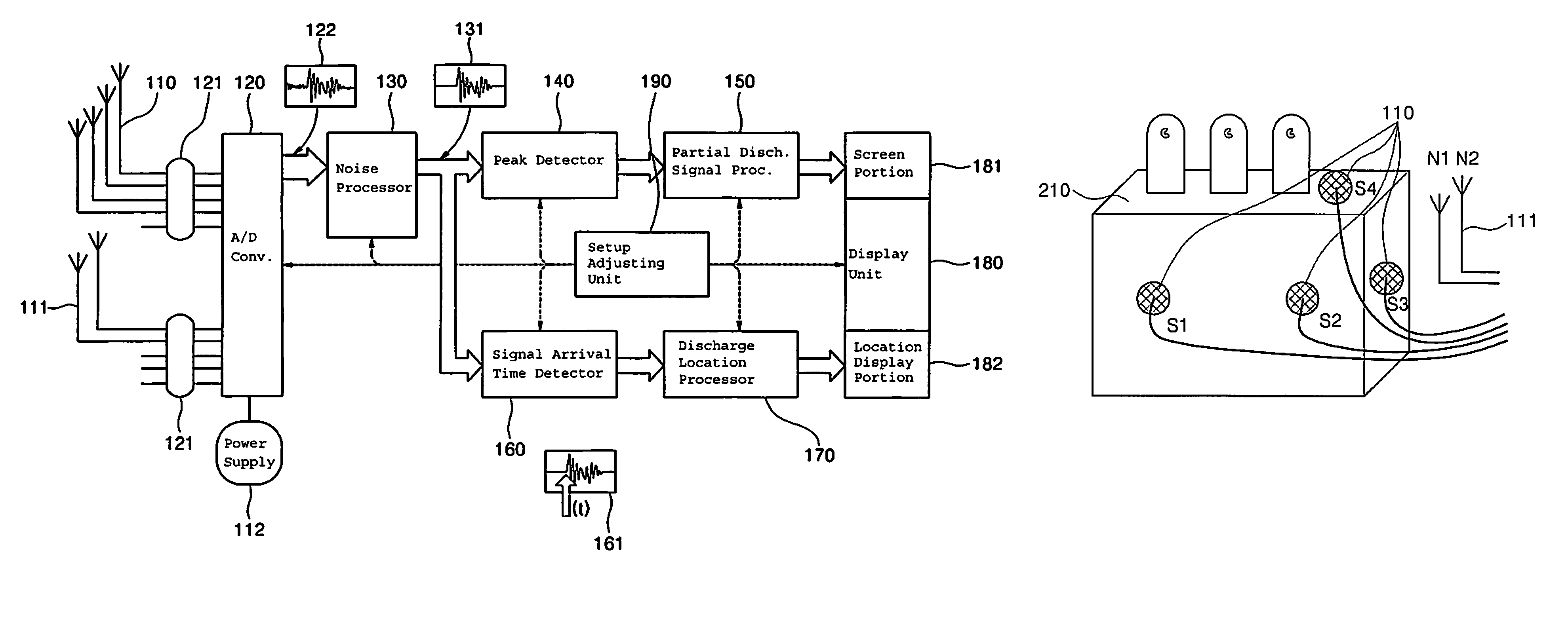
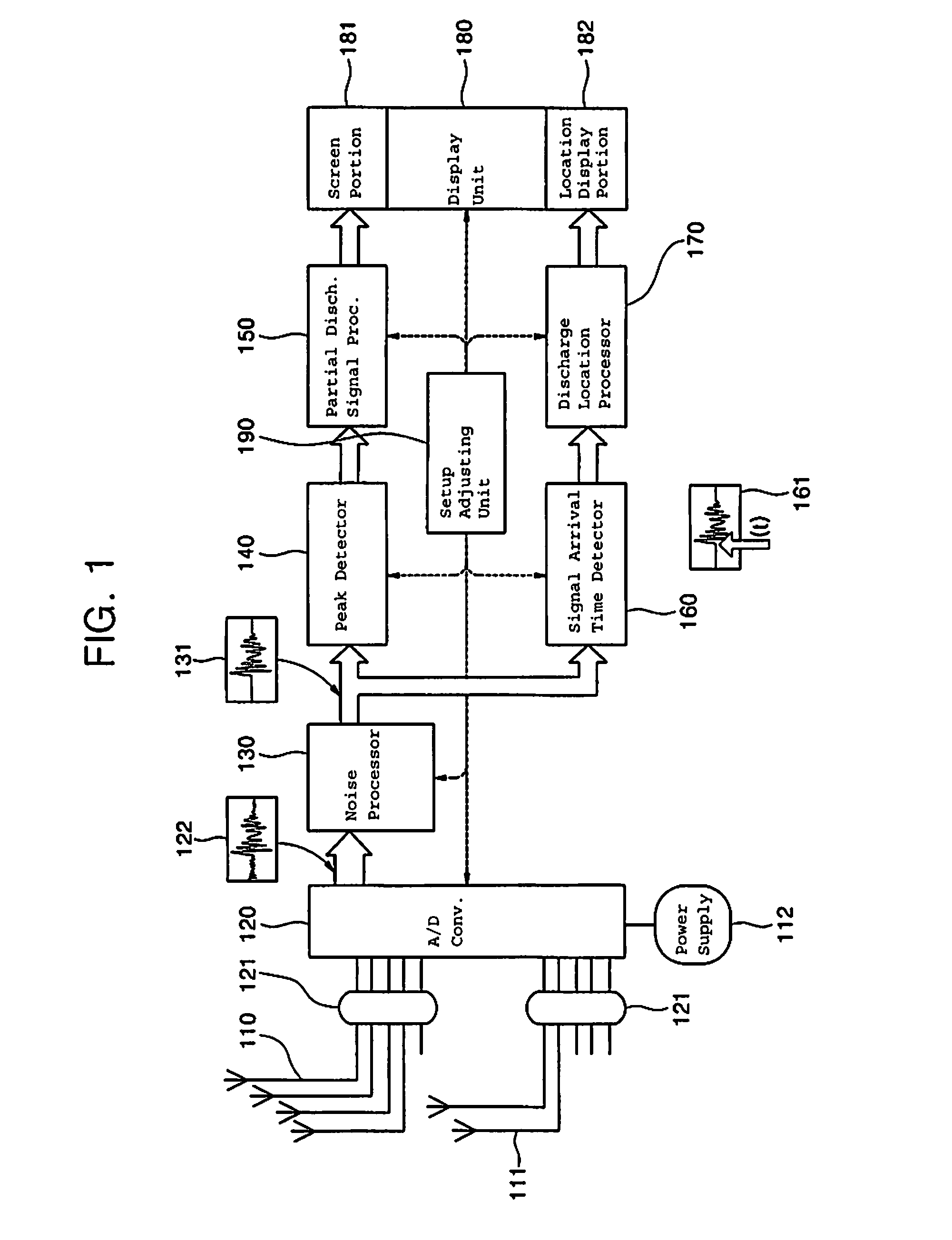
[0031]FIG. 1 is a block diagram illustrating a UHF partial discharge and its location measuring device for a high voltage power device according to an exemplary embodiment.

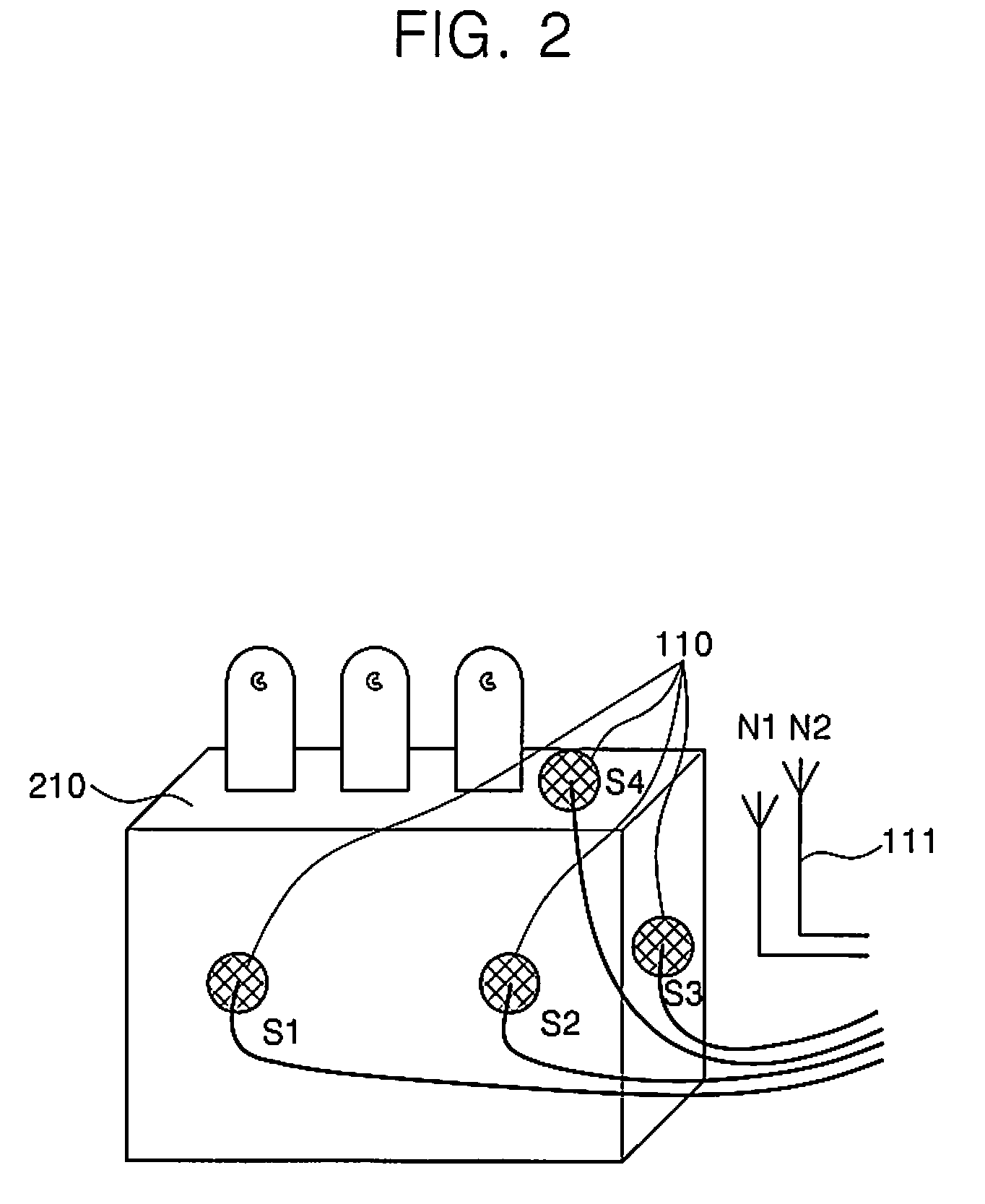
[0032]Referring to FIG. 1, the UHF partial discharge and its location measuring device includes a UHF partial discharge sensor 110, an external noise sensor 111, a high pass filter 121, an analog-digital converter 120, a power supply 112, a noise processor 130, a peak detector 140, a partial discharge signal processor 150, a signal arrival time detector 160, a discharge location processor 170, a display unit 180, and a setup adjusting unit 190.

[0033]The UHF partial discharge sensor 110 is attached to a DUT wh...


PUM


Abstract

Disclosed is a UHF partial discharge and its location measuring device for high-voltage power devices. The measuring device includes a partial discharge sensor, an external noise sensor, an analogue-digital converter, a peak detector, a partial discharge signal processor, an arrival time detector, a discharge location processor, and a display unit.

Description

PRIORITY[0001]This application claims priority from and the benefit of Korean Patent Application No. 10-2008-0096004, filed on Sep. 30, 2008, which is hereby incorporated by reference for all purposes as if fully set forth herein.BACKGROUND OF THE INVENTION[0002]1. Field of the Invention[0003]Disclosed exemplary embodiment is directed to technologies that may receive a partial discharge signal of an ultra-high frequency (“UHF”) band through a sensor to measure the partial discharge and display the location where the partial discharge occurred in a power device.[0004]2. Description of the Related Art[0005]Partial discharges occur mostly in a case where there is a defect inside a high-voltage power device such as oil-immersed transformers, gas insulating transformers, reactors, etc. There has been conventionally suggested a technology for measuring such partial discharges, which measures the arrival time of a sound wave signal transmitted from a location where the partial discharge oc...

Claims


Application Information

Patent Timeline
Patent Type & Authority Patents(United States)
IPC IPC(8): H01H9/50G01R31/08G01S3/80
CPCG01R31/1254G01R31/12
Inventor PARK, KI-JUNGOO, SUN-GEUNYOON, JIN-YULHAN, KI-SONJU, HYUNG-JUN
Owner KOREA ELECTRIC POWER CORP
Why Eureka
Try Eureka