
Inductance part

a technology of inductance parts and parts, applied in the direction of transformer/inductance details, basic electric elements, coils, etc., can solve the problems of insufficient use of only sheet coils and inability to achieve sandwich structures

Inactive Publication Date: 2011-08-30
SANKEN ELECTRIC CO LTD
View PDF6 Cites 27 Cited by
  • Summary
  • Abstract
  • Description
  • Claims
  • Application Information

AI Technical Summary

Benefits of technology

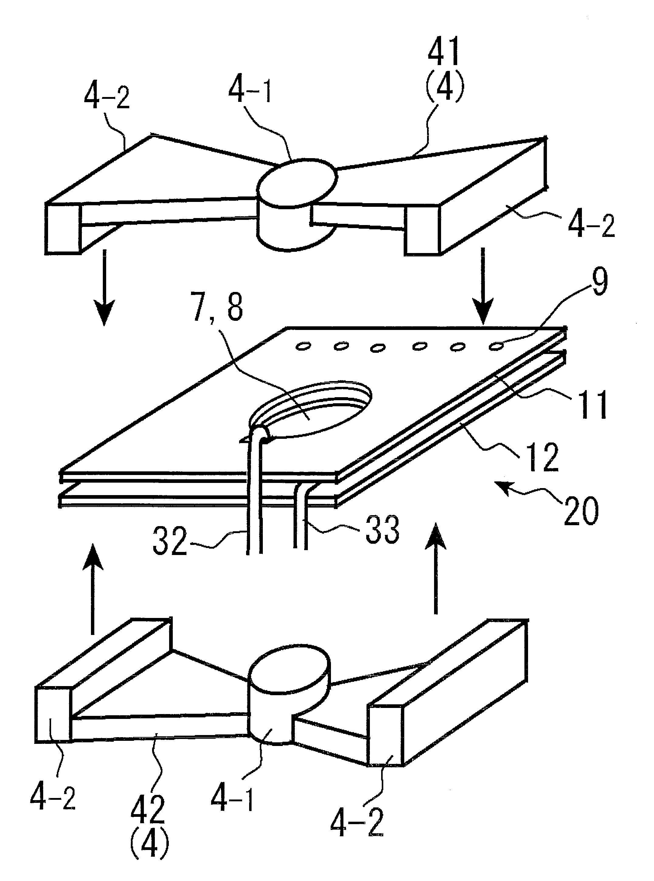
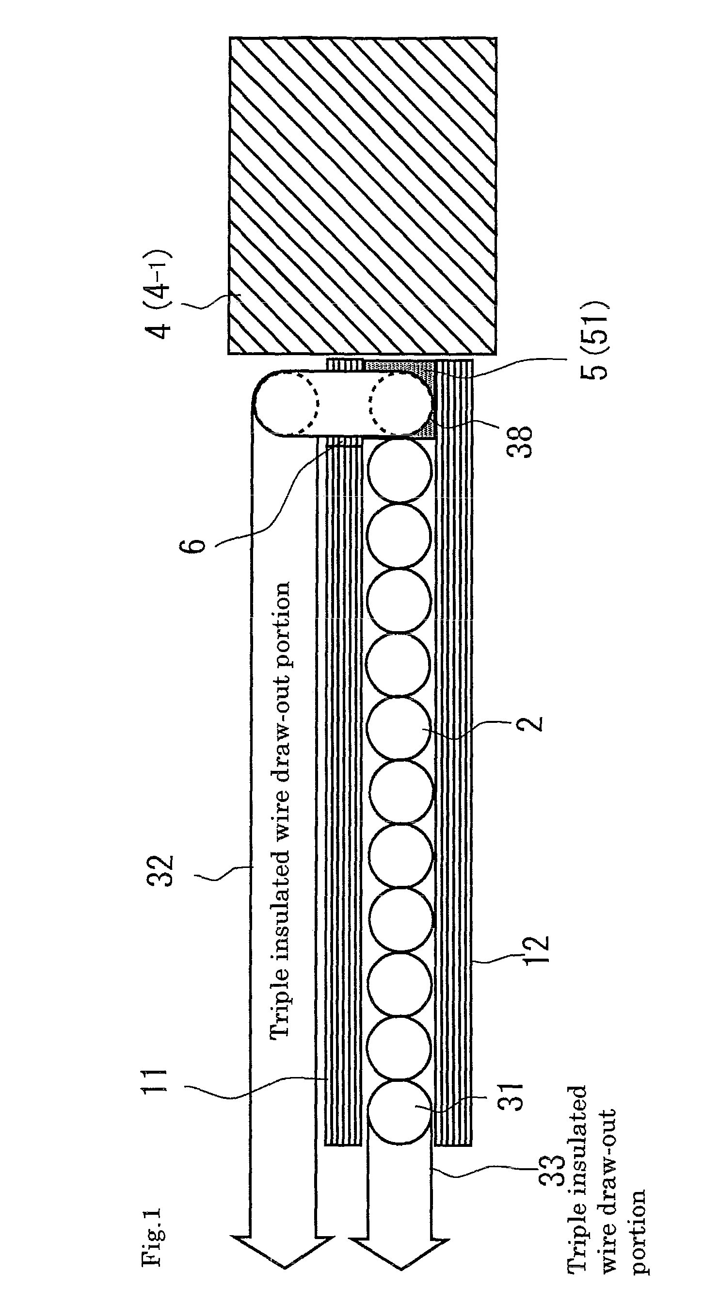
The present invention provides a structure that reduces leakage inductance and transformer thickness by tightly coupling a sheet coil and a winding wire. This is achieved by using an inductance part with a magnetic core, sheet coil, and insulated wire. The structure includes a bobbin with a hole for inserting the magnetic core and a cut portion for the draw-out wire, and a spacer for accommodating the winding. Another winding can be added on the opposite side of the bobbin. The draw-out wires of the windings are drawn out through the sheet coils without interfering with the close attachment between the sheet coil and winding wire. Overall, this structure achieves a satisfactory coupling between the sheet coil and winding wire, reducing leakage inductance and transformer thickness.

Problems solved by technology

However, a secondary winding has a low voltage and smaller number of turns but draws comparatively a larger current, so that there may occur a case where a use of only the sheet coil is not sufficient due to the limitation of output current rating.
When reduction of the thickness of the transformer is prioritized, the secondary winding can be provided only on one side, making it impossible to achieve the sandwich structure.

Method used


Image

  • Inductance part
  • Inductance part
  • Inductance part

Examples


first embodiment

(Second Modification of First Embodiment)

FIG. 5 illustrates a second modification in which the spacer is divided into a plurality of circular columns. As in the case of the first modification, a spacer 52 corresponding to the spacer 5 of the first modification is provided on the outer peripheral side of the winding 2. While the spacer 52 of the first modification has a ring shape, the spacer 52 of the second modification is constituted by a plurality of columnar-shaped spacers 53-1 to 53-4.

FIG. 6 illustrates an assembly state of the coil according to the second modification. As illustrated in FIG. 6, the spacers 53-1 to 53-4 are previously bonded to predetermined positions on the upper surface of the sheet coil 12. Further, the winding 2 formed by winding the triple insulated wire in a spiral manner is prepared. Then, the prepared winding 2 is fitted to a winding placement area which has been defined on the upper surface of the sheet coil 12 by the spacers 53-1 to 53-4 followed by b...

second embodiment

FIG. 7 is a cross-sectional view partly illustrating a winding structure of a transformer 50 according to a second embodiment of the present invention.

In FIG. 7, reference numerals 11 and 12 each denote a sheet coil, 25 and 26 denote windings constituted by one triple insulated wire, 25 is a winding wound on the upper surface side of the sheet coli 11, 26 is a winding wound between the sheet coils 11 and 12, and 5 and 5 each denote a spacer. Reference numerals 34 and 35 denote winding start portions of the windings 25 and 26 respectively, which are connected to each other through a cut portion 6 of the sheet coil 11 and cut portions 51 of the spacers 5. Reference numerals 36 and 37 each denote a triple insulated wire draw-out portion. Reference numeral 4 denotes a magnetic core (4-1 denotes a magnetic core portion positioned inside the winding).

When forming the transformer 50 according to the present embodiment, the sheet coils 11, 12 and spacers 5, 5 are bonded to construct a sheet...

third embodiment

FIG. 10 is a cross-sectional view partly illustrating a winding structure of a transformer 70 according to the third embodiment of the present invention.

In FIG. 10, reference numerals 13 and 14 each denote a sheet coil, 27 and 28 denote windings constituted by individual triple insulated wires, 27 is a winding wound between the sheet coils 13 and 14, 28 is a winding wound on the lower surface side of the sheet coil 14, 73 to 76 each denote a triple insulated wire draw-out portion, and 5 and 5 each denote a spacer. Reference numeral 4 denotes a magnetic core (4-1 denotes a magnetic core portion positioned inside the winding). A reference numeral 77 denotes a winding start portion of the winding 27, which is connected to the triple insulated wire draw-out portion 73 through a cut portion 61 of the sheet coil 13 and cut portion 51 of the spacer 5. A reference numeral 78 denotes a winding start portion of the winding 28, which is connected to the triple insulated wire draw-out portion 7...


PUM

PropertyMeasurementUnit
output voltageaaaaaaaaaa
inductanceaaaaaaaaaa

Abstract

Since there exists a draw-out portion of a triple insulated wire in a winding structure of a transformer in which the triple insulated wire is used as a secondary winding, the thickness of the transformer is increased by an amount corresponding to the wire diameter of the draw-out portion. Further, when reduction of the thickness of the transformer is prioritized, the secondary winding can be provided only on one side, making it impossible to achieve the sandwich structure. Thus, the coupling between the primary and secondary windings has been sacrificed. An inductance part provided with a magnetic core, two or more sheet coils, and a winding includes: a bobbin constituted by at least two or more sheet coils; and a winding formed by winding a triple insulated wire between the two or more sheet coils constituting the bobbin. A triple insulated wire draw-out portion on the center side of the winding is drawn out to one outer surface side of the bobbin.

Description

BACKGROUND OF THE INVENTION1. Field of the InventionThe present invention relates to an inductance part such as a transformer, a choke coil, and the like used for a power supply unit and, more particularly, to an inductance part provided with a plurality of windings and a magnetic core inserted through the windings.2. Description of the Related ArtWith a reduction in the weight, thickness, length and size of an electronic part, a switching power supply unit undergoes miniaturization and, accordingly, an inductance part which is a component used in the switching power unit is also required to be reduced in the thickness. Conventionally, as a transformer which is an inductance part, a sheet transformer as disclosed in Japanese Patent Application No. JP-A-62-76509 (refer to Patent Document 1) has been proposed. In general, a primary winding of a transformer used in a switching power supply has a large number of turns and draws less current, so that it is suitably used as a sheet coil. ...

Claims


Application Information

Patent Timeline
Patent Type & Authority Patents(United States)
IPC IPC(8): H01F5/00
CPCH01F27/2804H01F27/2828H01F27/2866H01F2027/2809H01F2027/2819
Inventor UTSUNO, MIZUKIMIYATA, TOMOHIROYAMAZAKI, SADAHIROISHII, SHIGENORI
Owner SANKEN ELECTRIC CO LTD
Learn More