
Free style deformation

a free style and deformation technology, applied in image data processing, complex mathematical operations, computation using non-denominational number representations, etc., can solve the problem of increasing the necessary size of the parameter set, the sensitivity of the ffd method to the initial placement of the control points, and the geometry inside the control volume deformation, so as to reduce the distance between the first sub-design and the second sub-design.

Inactive Publication Date: 2011-08-30
HONDA RES INST EUROPE
View PDF5 Cites 1 Cited by
  • Summary
  • Abstract
  • Description
  • Claims
  • Application Information

AI Technical Summary

Benefits of technology

The present invention provides an improved method and system for manipulating a design. The method involves introducing structural changes in a design or reorganizing the representation using a free form deformation geometry and a control volume that is variable and adaptive. The method may also include adapting the control volume to minimize the distance between different parts of the design. The invention also provides a database of pre-calculated geometries that can be used for optimizing the design. The methods can be used for optimizing real-world objects, such as fluid dynamic objects. The invention introduces a modular concept for design modifications that combines common techniques and replaces modules to efficiently and flexibly represent complex structures.

Problems solved by technology

A modification in the positions of the control point results in a deformation of the geometry inside the control volume.
One main disadvantage of the FFD method is its sensitivity to the initial placement of the control points.
An inappropriate set-up increases the necessary size of the parameter set; and therefore, increases the dimensionality of the search space.
One of the reasons for the inappropriate set-up is that the influence of a control point on an object decreases as the distance from the object increases.
The large modification of the control point in turn often modifies other areas of the design space that has to be compensated for by moving other control points.
First, using the FFD, it is only possible to deform a design given initially.
That is, the possible shape modifications are limited by the design which was initially chosen for deformation.
Conceptual or structural changes are very difficult to achieve.
For example, introduction of holes or edges is either impossible or requires a huge amount of modification to the control points.
Additionally, this process is very difficult and even impossible when dealing with designs that are not allowed to include holes in the represented space.
This problem occurs when the FFD is used for deforming systems that are analyzed with computational calculation methods such as Computational Fluid Dynamics (CFD) or Finite Element Methods (FEM) to calculate specific features of the design.
In the standard FFD method, this is not possible without a remeshing procedure that is very time consuming.
Issues often arise when control points must be moved for a significant distance to reflect a desired design change.
Such moving of the control points results in a control point set that is very ill-structured because many control points are quite close to each other.
If control points are very close, further design modifications are very difficult to achieve without having loops in the geometry.

Method used


Image

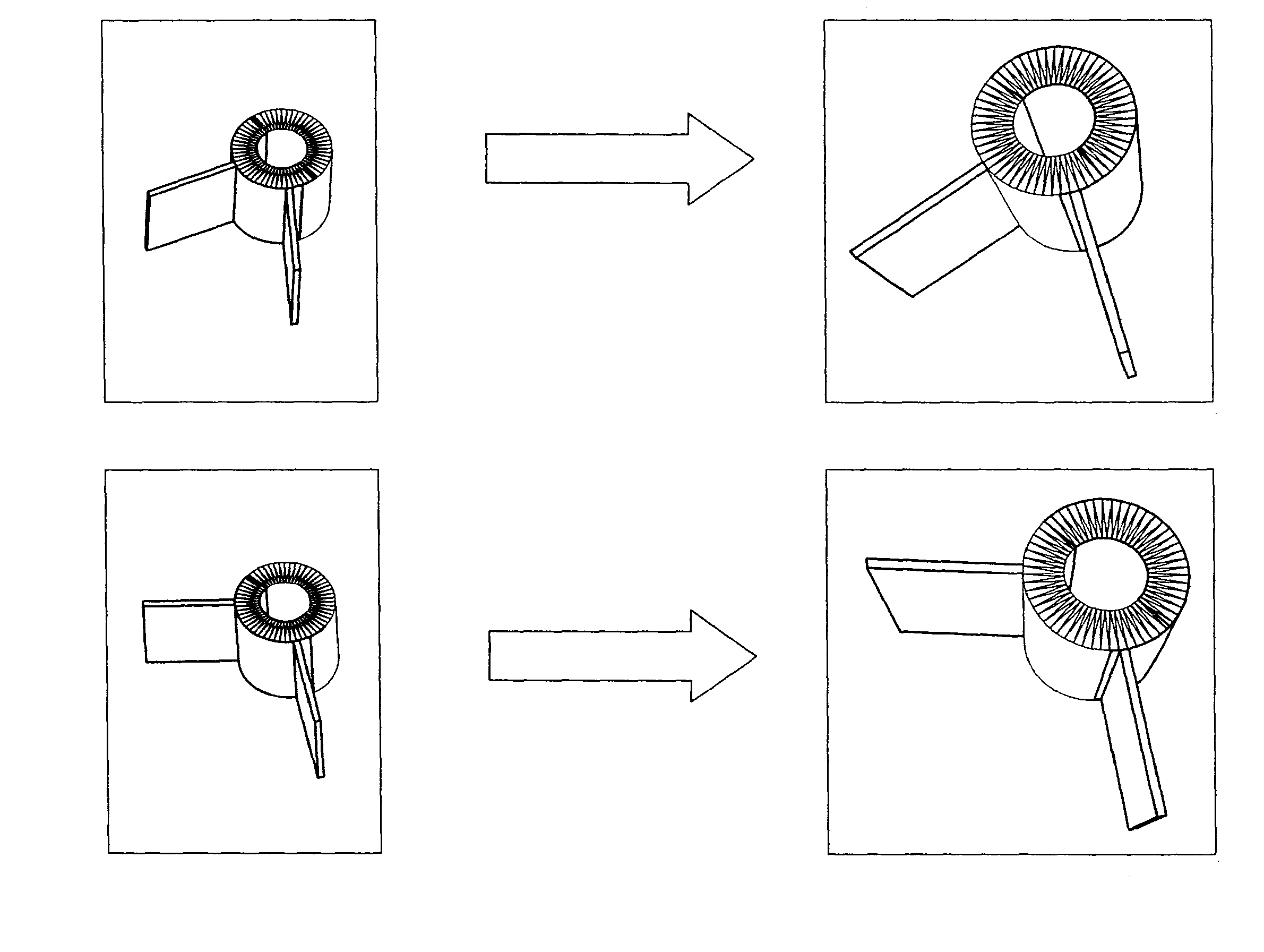
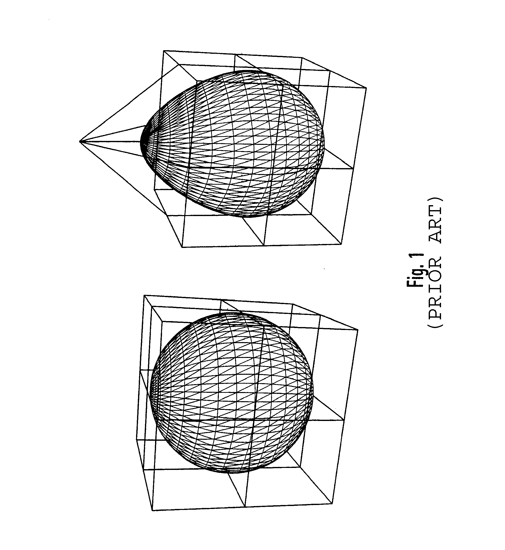
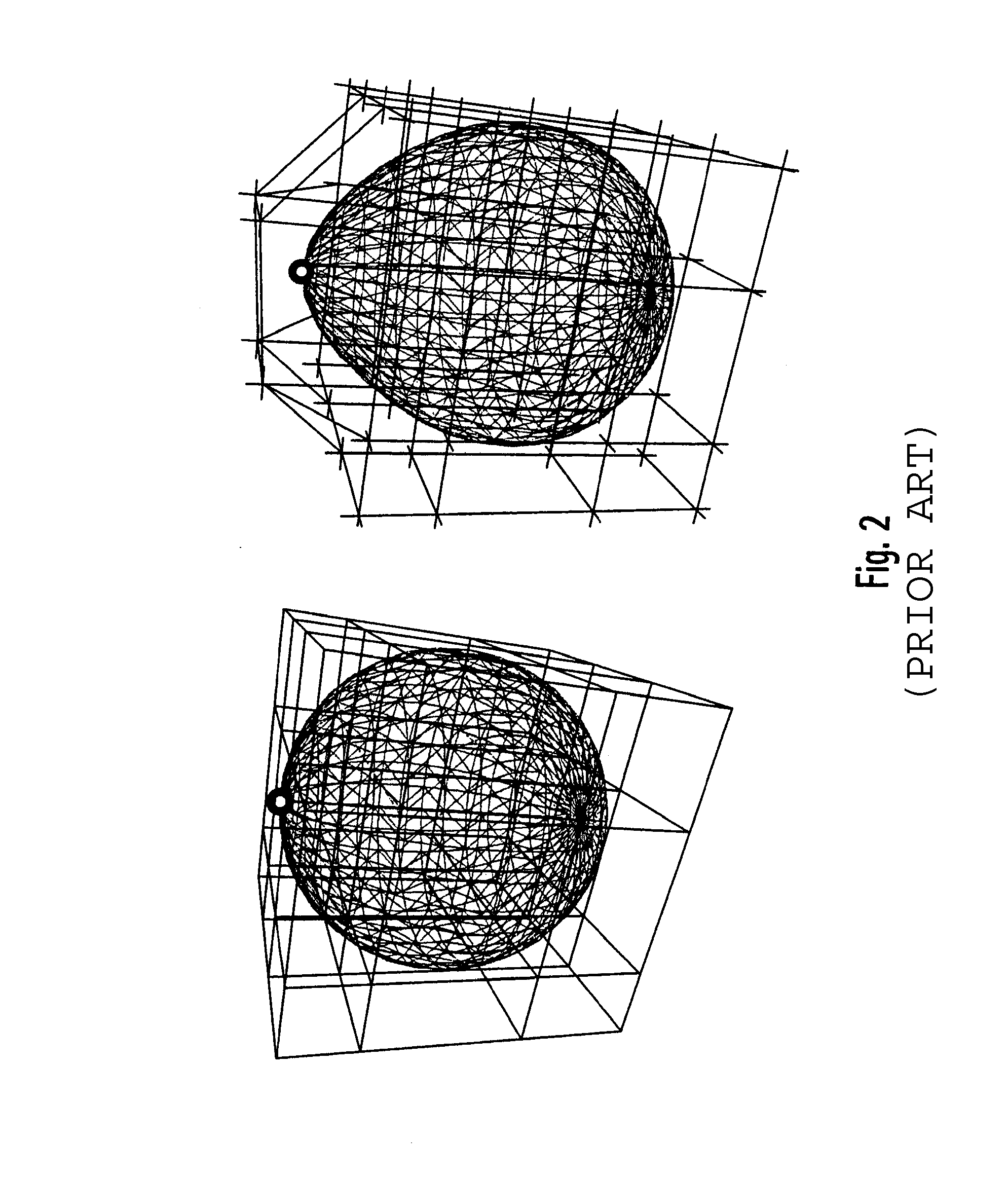
  • Free style deformation
  • Free style deformation
  • Free style deformation

Examples


Embodiment Construction

[0037]Reference in the specification to “one embodiment” or to “an embodiment” means that a particular feature, structure, or characteristic described in connection with the embodiments is included in at least one embodiment of the invention. The appearances of the phrase “in one embodiment” in various places in the specification are not necessarily all referring to the same embodiment.

[0038]Some portions of the detailed description that follows are presented in terms of algorithms and symbolic representations of operations on data bits within a computer memory. These algorithmic descriptions and representations are the means used by those skilled in the data processing arts to most effectively convey the substance of their work to others skilled in the art. An algorithm is here, and generally, conceived to be a self-consistent sequence of steps (instructions) leading to a desired result. The steps are those requiring physical manipulations of physical quantities. Usually, though no...


PUM


Abstract

A method for modifying an object design using a computer comprises the steps of: selecting a first sub-design of the object design comprising a first free form deformation geometry and a first free deformation control volume that is variable and adaptive; choosing a second sub-design comprising a second free form deformation geometry; and replacing the first geometry with the second geometry.

Description

FIELD OF THE INVENTION[0001]The present invention relates to the deformation of objects using an extension of free form deformation (FFD) that can be applied to computer graphics or to optimize real-world designs.BACKGROUND OF THE INVENTION[0002]Free Form Deformation (FFD) techniques have been introduced to manipulate objects in computer graphics and computer animations. The FFD has been applied to optimize shapes of aerodynamic objects in conjunction with evolutionary algorithms. The FFD techniques is known to provide a reasonable compromise in the flexibility of shapes and a small number of parameters, which in turn results in a small dimensional search space for the optimization. Furthermore, it has been demonstrated that the shape deformations defined by the FFD techniques can be applied equally well to deform a grid for computational fluid dynamics calculations. Using the FFD techniques, it is possible to obviate generating of the manual grid even for complex geometries. In man...

Claims


Application Information

Patent Timeline
Patent Type & Authority Patents(United States)
IPC IPC(8): G06T15/00
CPCG06T19/00G06T19/20G06T2219/2021
Inventor SENDHOFF, BERNHARDOLHOFER, MARKUSMENZEL, STEFAN
Owner HONDA RES INST EUROPE
Learn More