Molded waveguides

a waveguide and waveguide technology, applied in the direction of circuit masks, chemical vapor deposition coatings, capsule delivery, etc., can solve the problems of limited materials suitable for reactive ion etching masks, difficult to etch relatively precisely, and inability to etch vertical channels,

Inactive Publication Date: 2011-09-06
PRESIDENT & FELLOWS OF HARVARD COLLEGE
View PDF55 Cites 66 Cited by
  • Summary
  • Abstract
  • Description
  • Claims
  • Application Information

AI Technical Summary

Problems solved by technology

That is, with wet etching it can be difficult to etch relatively precise, vertical channels in a surface.
Thus, materials suitable for reactive ion etching masks are limited.
Many metal masks, such as gold masks, are unsuitable since the metals can sputter easily.
Such procedures can be costly.
However, problems associated with this technique include softening and deformation of the cladding or substrate under temperatures required for injection molding.
Fabrication with precision is compromised, typically.
This technique requires expensive and complicated photolithographic systems for base formation of the waveguide array, and subsequent multi-step processing is required such as removal of the polymeric film from the substrate, lamination processing, curing processing, and other processing steps.
While the above techniques represent, in some cases, useful advances in the art, many of these techniques require relatively sophisticated apparatus, are expensive, and generally consume more reactants and produce more by-products in collateral fabrication steps than is optimal, and / or lack optimal versatility in application.

Method used


Image

  • Molded waveguides
  • Molded waveguides
  • Molded waveguides

Examples


Embodiment Construction

[0069]U.S. patent application Ser. No. 09 / 634,201, filed Aug. 9, 2000 and U.S. patent application Ser. No. 09 / 004,583, filed Jan. 8, 1998 (now U.S. Pat. No. 6,355,198) and U.S. application Ser. No. 08 / 616,929, filed Mar. 15, 1986 and U.S. provisional application Ser. No. 60 / 046,689 filed May 16, 1997, all are incorporated herein by reference.

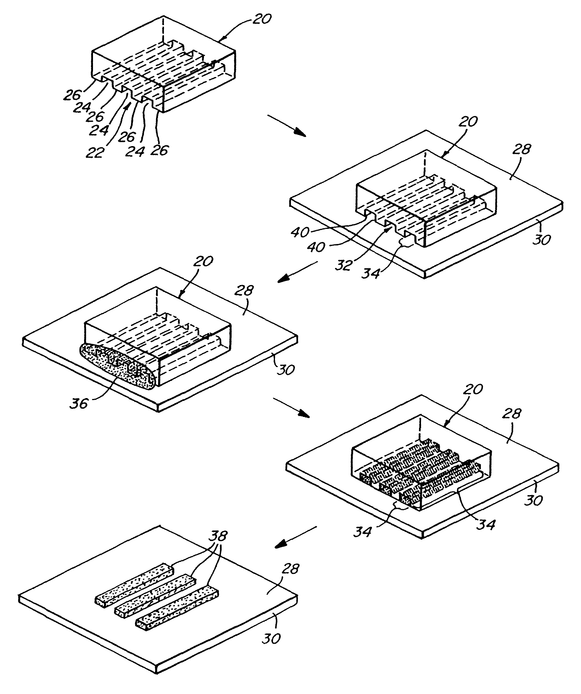
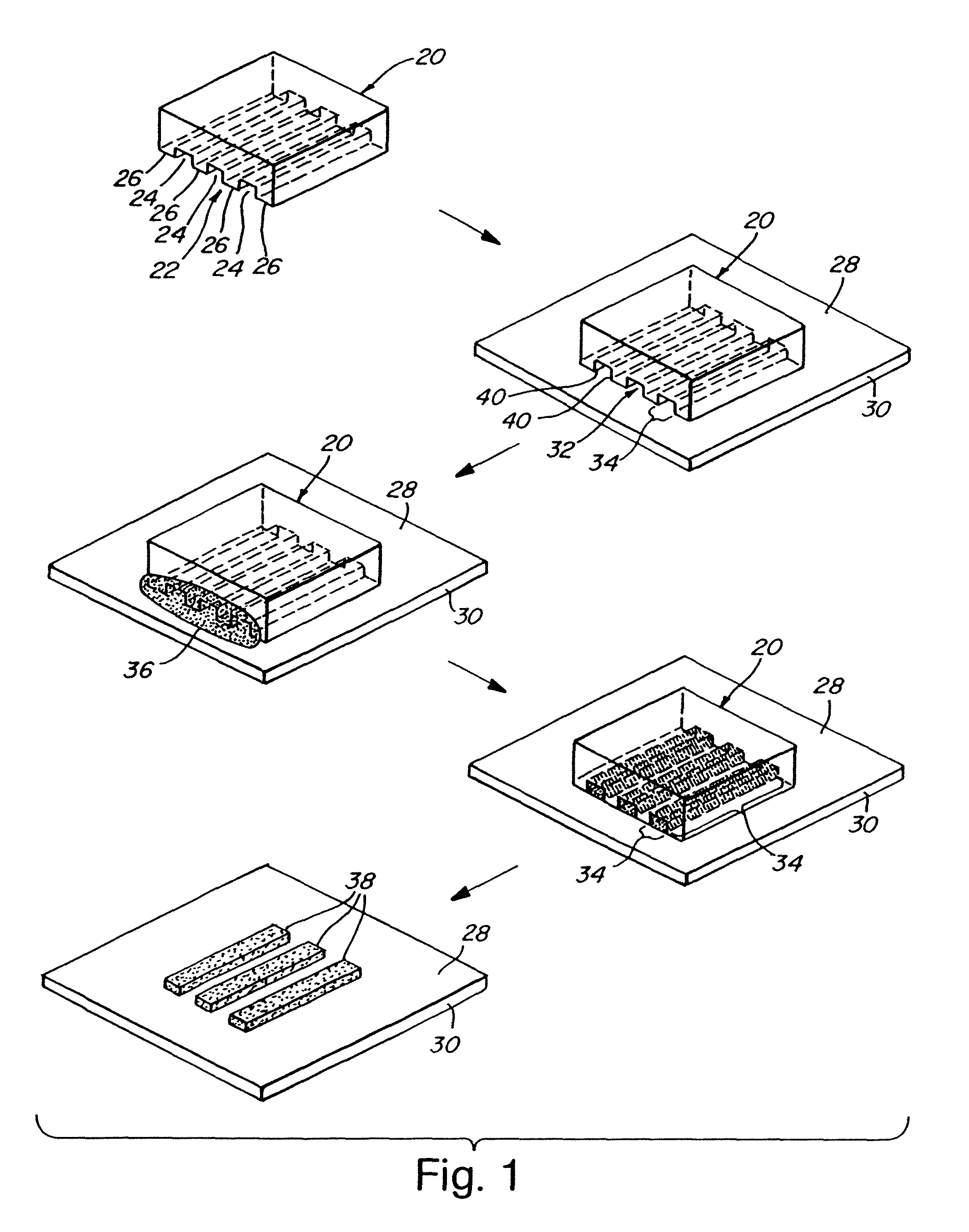
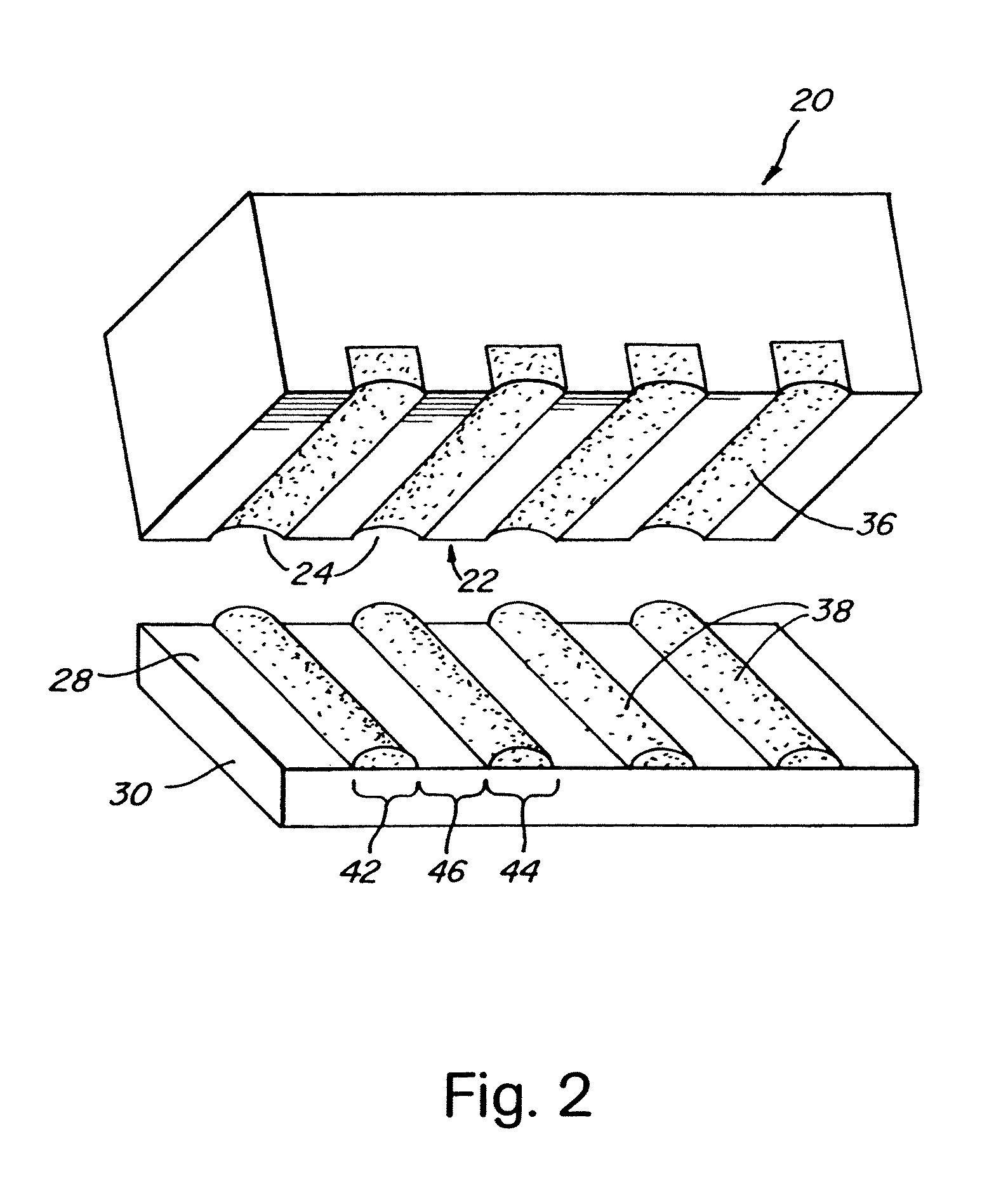
[0070]The present invention provides, in one aspect, techniques for placement, at regions proximate a substrate surface, of chemically or biochemically active agents, fluid precursors of articles such as waveguides to be immobilized proximate a substrate surface, and / or other species desirably transferred to a region or regions proximate a substrate surface in a pattern. “Fluid precursor”, as used herein, means a material that is fluid enough that it can be formed into a pattern using a forming article, using techniques described herein. The invention utilizes an applicator having a pattern of indentations that can be used to transfer such a spe...


PUM

PropertyMeasurementUnit
temperatureaaaaaaaaaa
room temperatureaaaaaaaaaa

Abstract

Chemically or biochemically active agents or other species are patterned on a substrate surface by providing a micromold having a contoured surface and forming, on a substrate surface, a chemically or biochemically active agent or fluid precursor of a structure. A chemically or biochemically active agent or fluid precursor also can be transferred from indentations in an applicator to a substrate surface. The substrate surface can be planar or non-planar. Fluid precursors of polymeric structures, inorganic ceramics and salts, and the like can be used to form patterned polymeric articles, inorganic salts and ceramics, reactive ion etch masks, etc. at the surface. The articles can be formed in a pattern including a portion having a lateral dimension of less than about 1 millimeter or smaller. The indentation pattern of the applicator can be used to transfer separate, distinct chemically or biochemically active agents or fluid precursors to separate, isolated regions of a substrate surface. Waveguide arrays, combinatorial chemical or biochemical libraris, etc. can be made. Differences in refractive index of waveguide and cladding can be created by subjecting the waveguide and cladding, made of indentical prepolymeric material, to different polymerization or cross-linking conditions. Interferometers are defined by coupling arrays of waveguides, where coupling can be controlled by altering the difference in refractive index between cladding and waveguide at any desired location of the array. Alteration and refractive index can be created photochemically, chemically, or the like. Sensors also are disclosed, including biochemical sensors.

Description

RELATED APPLICATIONS[0001]This application is a continuation of U.S. patent application Ser. No. 12 / 001,564, filed Dec. 12, 2007, which is a divisional of U.S. patent application Ser. No. 10 / 677,103, filed Oct. 1, 2003, which is a divisional of U.S. patent application Ser. No. 09 / 634,201, filed Aug. 9, 2000 (now U.S. Pat. No. 6,660,192); which is a divisional of U.S. patent application Ser. No. 09 / 004,583, filed Jan. 8, 1998 (now U.S. Pat. No. 6,355,198); which is a continuation-in-part of U.S. application Ser. No. 08 / 616,929, filed Mar. 15, 1996 (abandoned); Ser. No. 09 / 004,583 also claim priority under 35 U.S.C.§119(e) of the benefit of U.S. provisional application Ser. No. 60 / 046,689 filed May 16, 1997, all of which are incorporated herein by reference.STATEMENT AS TO POTENTIAL RIGHTS UNDER FEDERALLY SPONSORED RESEARCH AND DEVELOPMENT[0002]Research leading to the invention disclosed and claimed herein was supported in part by the Office of Naval Research, ONR Contract No. N00014-...

Claims


Application Information

Patent Timeline
Patent Type & Authority Patents(United States)
IPC IPC(8): B29D11/00B29C35/08B29C43/00B29C45/14D04H1/20G02B1/12G02B6/10G02B6/00B29C39/00C23F1/00C03C25/68C03C15/00B44C1/22B28B1/14B29C41/00A61K9/51A61K47/48B01J19/00B29C31/04B29C33/42B29C37/00B29C39/24B29C67/24B81C1/00C40B60/14G02B6/138H05K3/00H05K3/06
CPCA61K47/48992B01J19/0046B29C31/04B29C37/0053B29C39/24B29C43/021B29C67/246B29D11/00346B29D11/00663B81C1/00031B81C1/00206B81C99/0085B82Y30/00G02B6/138B01J2219/00382B01J2219/00416B01J2219/0043B01J2219/00466B01J2219/00605B01J2219/0061B01J2219/00612B01J2219/00619B01J2219/00626B01J2219/0063B01J2219/00637B01J2219/00648B01J2219/00659B01J2219/00713B29C33/42B29K2105/0002B29L2011/0016B81B2201/0214B81C2201/034C40B60/14G01N21/7703G01N2021/7776H05K3/0079H05K3/061A61K47/6957
Inventor KIM, ENOCHXIA, YOUNANMRKSICH, MILANJACKMAN, REBECCA J.ZHAO, XIAO-MEISMITH, STEPHEN P.MARZOLIN, CHRISTIANPRENTISS, MARA G.WHITESIDES, GEORGE M.
Owner PRESIDENT & FELLOWS OF HARVARD COLLEGE
Why Eureka
Try Eureka