Microscope apparatus with fluorescence cube for total-internal-reflection fluorescence microscopy

a technology of fluorescence microscopy and microscopy apparatus, which is applied in the field of microscopy apparatus and fluorescence cube, can solve the problems of large size and high cost of microscopy

Active Publication Date: 2011-09-06
NIKON CORP
View PDF6 Cites 3 Cited by
  • Summary
  • Abstract
  • Description
  • Claims
  • Application Information

AI Technical Summary

Benefits of technology

[0007]The present invention makes it possible to provide a microscope apparatus capable of exchanging from a confocal microscope to a total-internal-reflection fluorescence microscope by changing a fluorescence cube used in a fluorescence microscope, and a fluorescence cube capable of exchanging from a confocal microscope to a total-internal-reflection fluorescence microscope.

Problems solved by technology

Accordingly, a large exchanging mechanism is necessary, so that the microscope becomes large and expensive.

Method used


Image

  • Microscope apparatus with fluorescence cube for total-internal-reflection fluorescence microscopy
  • Microscope apparatus with fluorescence cube for total-internal-reflection fluorescence microscopy
  • Microscope apparatus with fluorescence cube for total-internal-reflection fluorescence microscopy

Examples


first embodiment

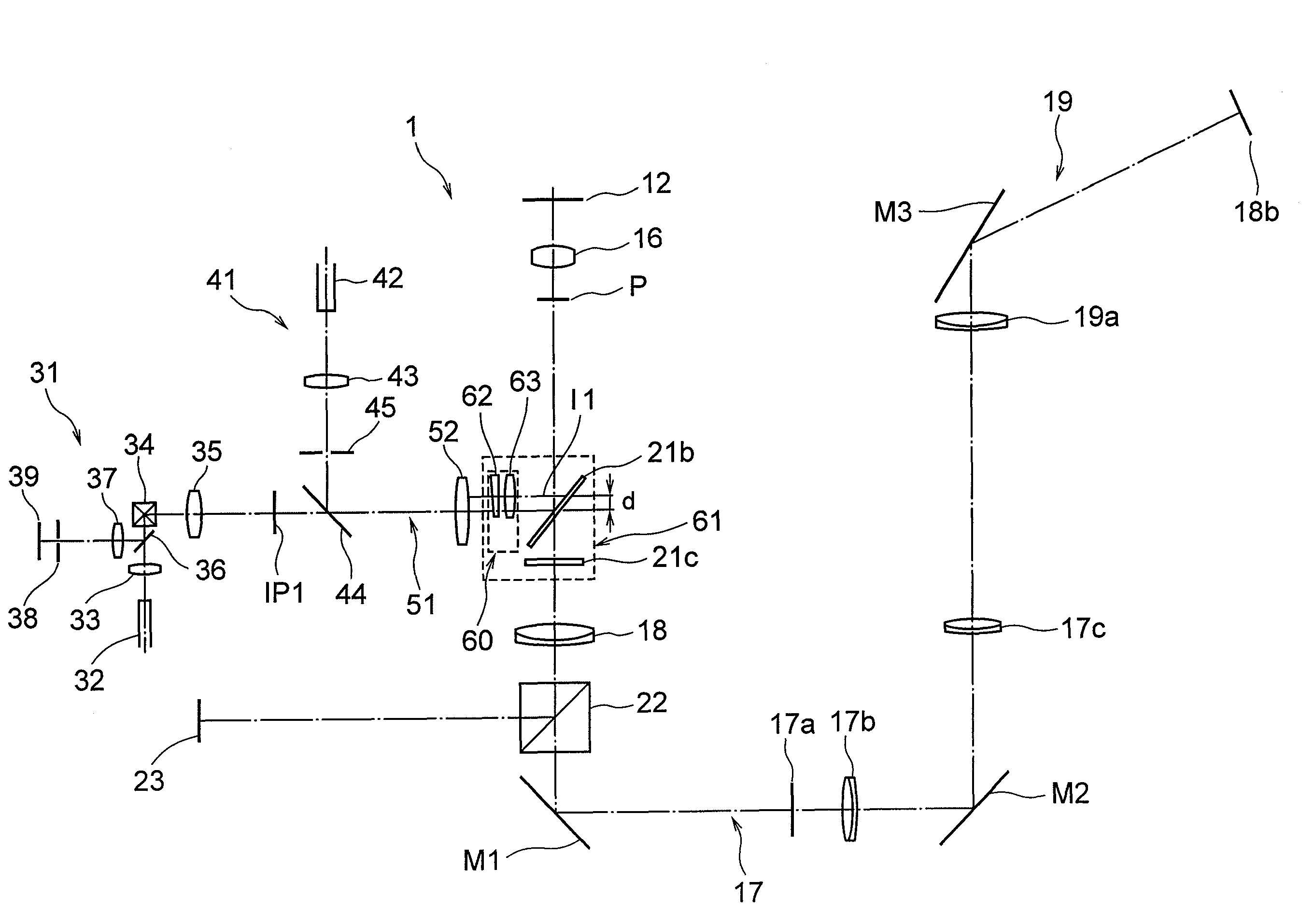
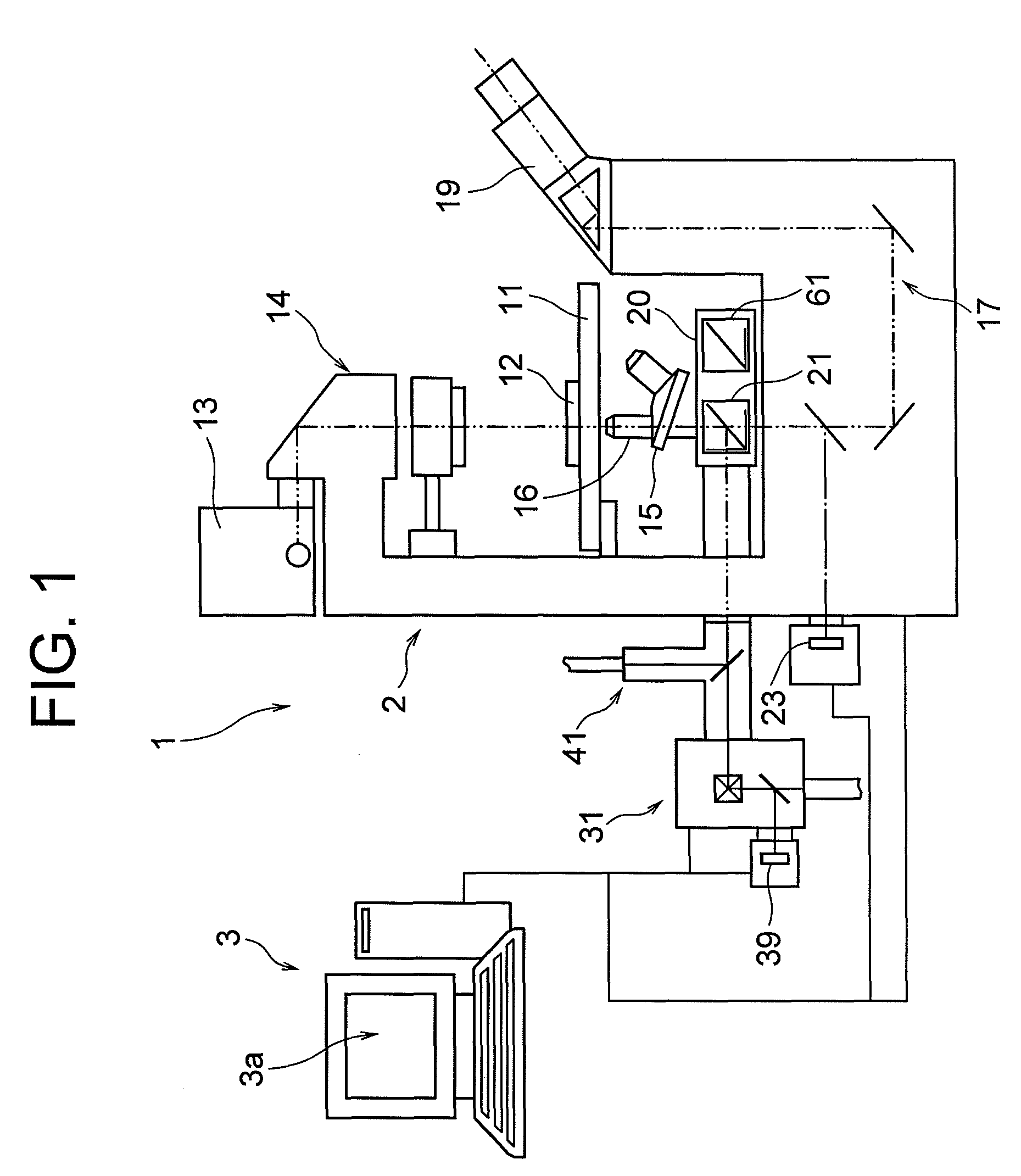
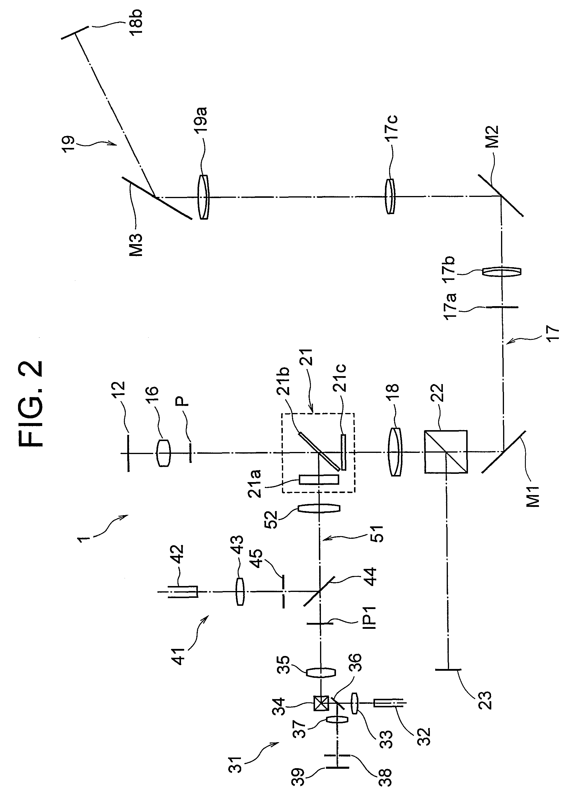
[0015]FIG. 1 is a schematic diagram showing a microscope apparatus according to a first embodiment. FIG. 2 is a diagram showing an optical system of the microscope apparatus according to the first embodiment. FIG. 3 is a diagram showing an optical system of the microscope apparatus according to the first embodiment upon changing to a total-internal-reflection microscope. FIGS. 4A, 4B, 4C are diagrams explaining an effect of an optical member of the microscope apparatus, in which FIG. 4A is explaining a confocal scanning illumination state or an epi-illumination state, FIG. 4B is explaining a total-internal-reflection illumination state, and FIG. 4C is explaining a wedge prism effect. In FIGS. 2 and 3, a transmission illumination optical system explained later is omitted.

[0016]In FIGS. 1 through 4C, a microscope apparatus 1 is composed of an inverted fluorescence microscope body 2 (hereinafter simply called a microscope), and a control apparatus 3 (hereinafter called a PC) constructe...

second embodiment

[0044]Then a microscope apparatus according to a second embodiment is explained with reference to accompanying drawings. Schematic configuration of the microscope apparatus is similar to the first embodiment, so that figures and explanations are omitted.

[0045]FIG. 5 is a diagram showing an optical system of the microscope according to the second embodiment. FIG. 6 is a diagram showing an optical system of the microscope apparatus according to the second embodiment upon changing to a total-internal-reflection microscope.

[0046]In FIG. 5, using procedures upon using the microscope apparatus 101 as a transmission microscope is the same as the first embodiment, so that duplicated explanations are omitted.

[0047]Then, a case where the microscope apparatus 101 is used as a scanning microscope is explained with reference to FIG. 5.

[0048]When the microscope apparatus 101 is used as a scanning microscope, in the confocal scanning observation system 31, laser light from an unillustrated laser l...


PUM


Abstract

A microscope apparatus has an illumination optical system illuminating a sample with laser light from laser light sources. A fluorescence detection optical system detects fluorescence from the sample. Fluorescence cubes are interchangeably provided in an optical path of the illumination optical system and lead the laser light to the sample. An objective lens is also provided. At least one of the fluorescence cubes includes an optical member that makes a principal ray of the laser light substantially parallel to an optical axis of the illumination optical system and concentrates the laser light on a given position that is on a pupil position of the objective lens and separated from the optical axis, thereby providing a microscope apparatus capable of changing from a confocal microscope to a total-internal-reflection fluorescence microscope by exchanging a fluorescence cube used in the fluorescence microscope.

Description

CROSS-REFERENCE TO RELATED APPLICATION[0001]This application is a continuation of International Application No. PCT / JP2008 / 055627 filed Mar. 18, 2008.TECHNICAL FIELD[0002]The present invention relates to a microscope apparatus and a fluorescence cube installed therein.BACKGROUND ART[0003]A confocal microscope and a total-internal-reflection fluorescence microscope are widely used for observing living cells, and commonly use a laser light source. There has been proposed a microscope that can be commonly used for a confocal microscope and a total-internal-reflection fluorescence microscope (see, for example, Japanese Patent Application Laid-Open No. 2005-121796).[0004]However, in the conventional microscope, upon changing a confocal microscope to a total-internal-reflection fluorescence microscope, an optical member for converging laser light to a total-internal-reflection condition area on a pupil position of an objective lens has to be inserted to an illumination optical system. Acc...

Claims


Application Information

Patent Timeline
Patent Type & Authority Patents(United States)
IPC IPC(8): G02B21/06
CPCG02B21/0076G02B21/008G01N21/6458
Inventor NIHOSHI, TOSHIAKI
Owner NIKON CORP
Why Eureka
Try Eureka