Power conversion systems

a technology of power conversion and power conversion fluid, which is applied in the direction of machines/engines, mechanical equipment, greenhouse gas reduction, etc., can solve the problems of adding complexity to the component in the cycle to receive solar energy and heat the working fluid, and achieve the effect of improving efficiency

Inactive Publication Date: 2011-09-13
BRAYTON ENERGY
View PDF9 Cites 28 Cited by
  • Summary
  • Abstract
  • Description
  • Claims
  • Application Information

AI Technical Summary

Problems solved by technology

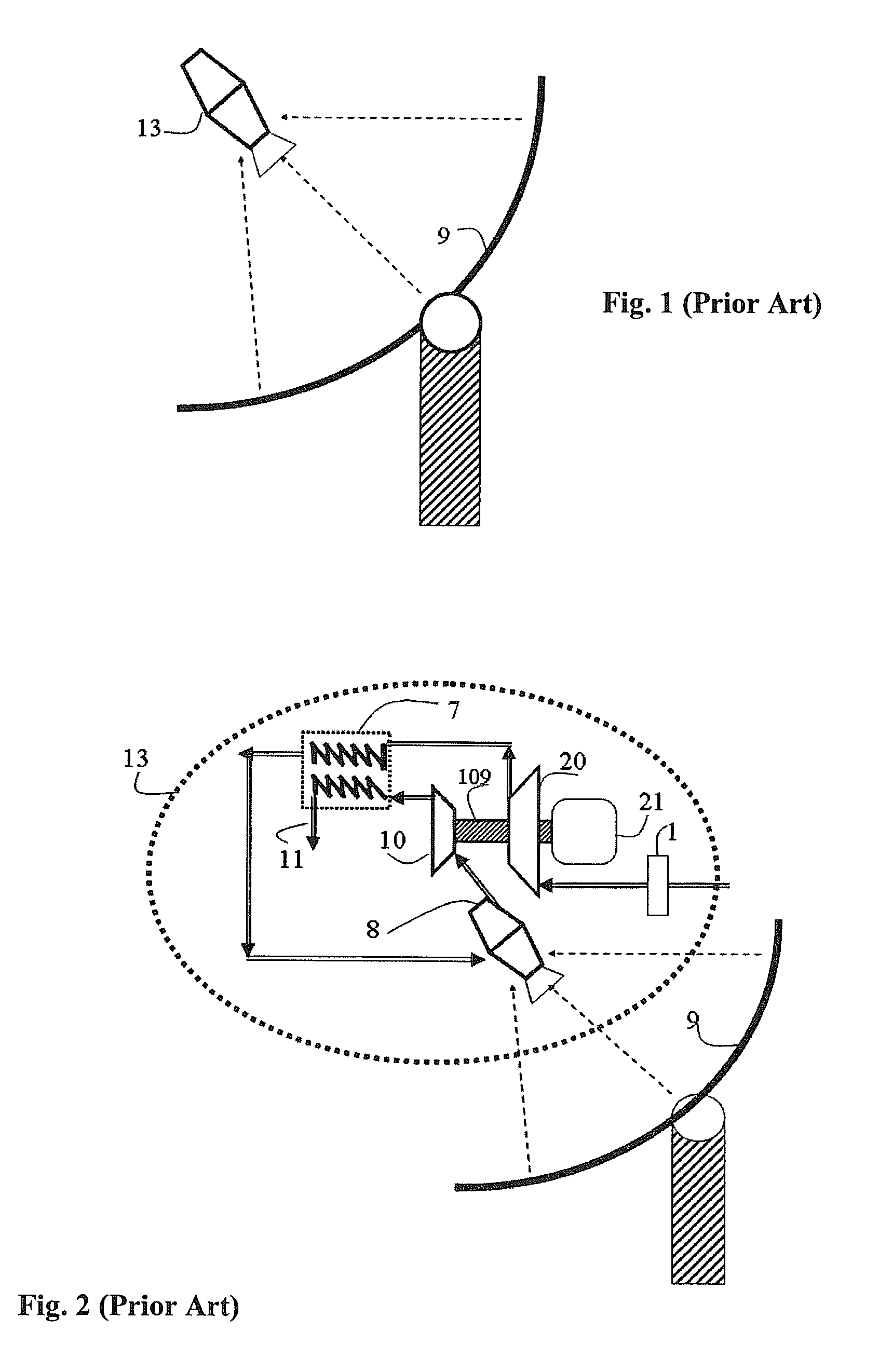
In summary, the solar-activated “Dish-Brayton” module operates precisely as a conventional gas turbine generation unit, with the added complexity of a component in the cycle to receive solar energy and heat the working fluid.

Method used


Image

  • Power conversion systems
  • Power conversion systems
  • Power conversion systems

Examples


Embodiment Construction

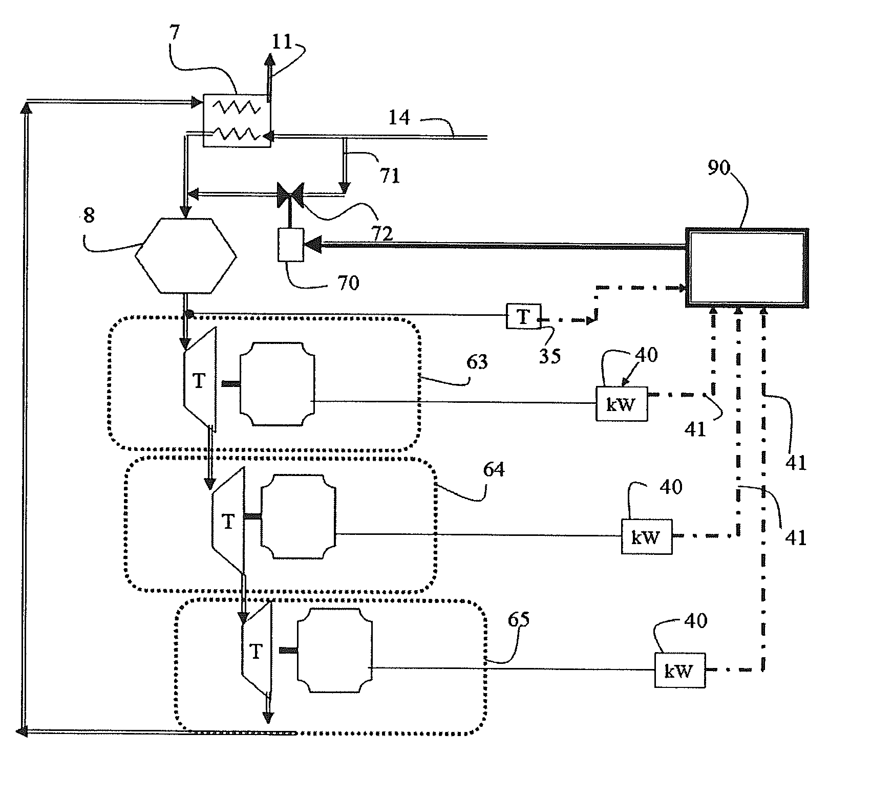
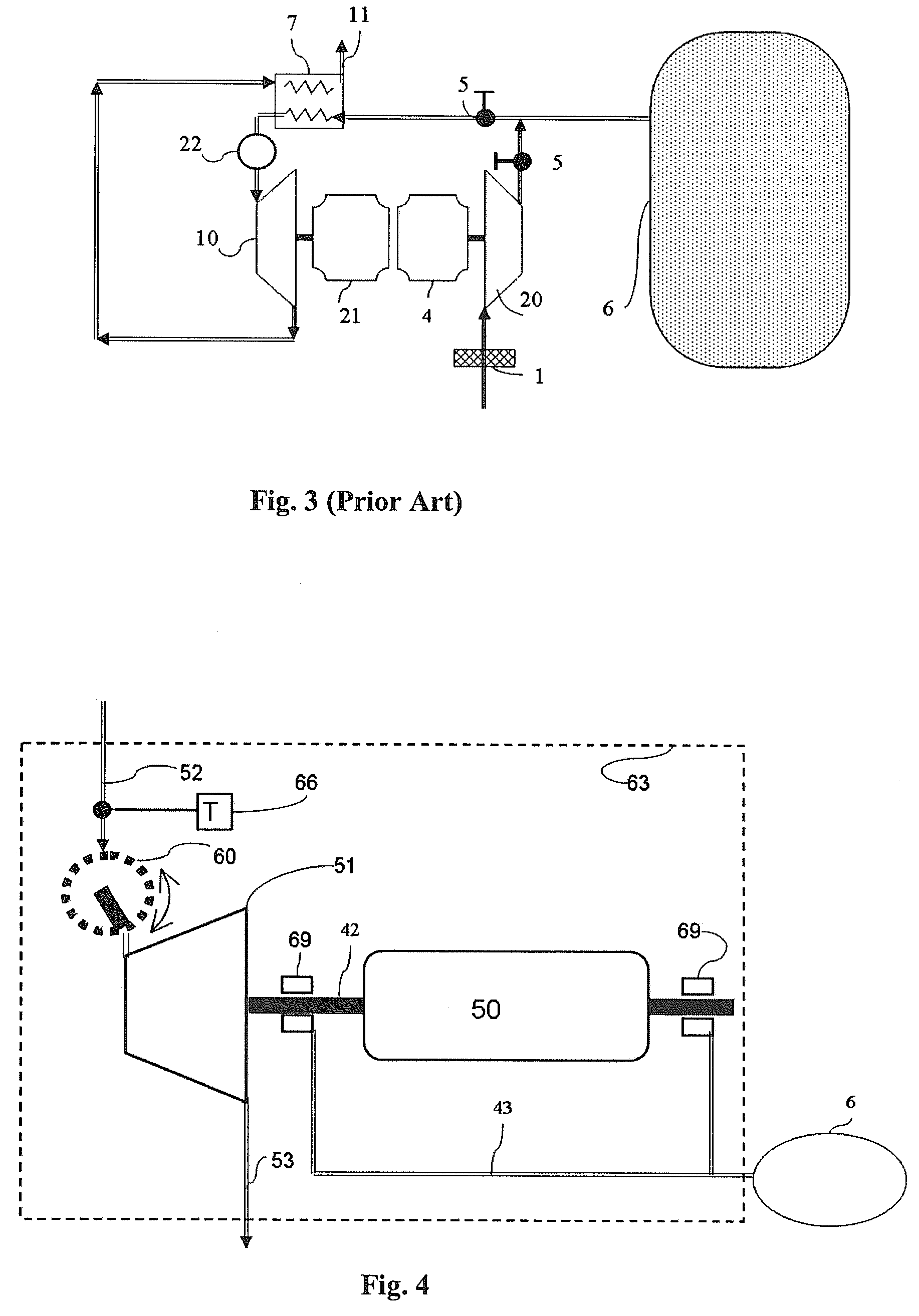
[0035]A turbo-alternator is a device that extracts energy from an expanding gas, creating shaft power to be converted to electrical energy. FIG. 4 is a schematic representation of a typical turbo-alternator. The turbo-alternator 63 includes a turbine 51 and an alternator 50 on a common shaft 42 supported by bearings 69. The invention will be described herein primarily in reference to the embodiments wherein an alternator is employed, indicating a preferred type of electrical power generator, however, it will be recognized that an alternator is not the only type that can be used in the embodiments described herein and that and all manner of electrical power generators are contemplated. The alternator 50 converts the shaft power derived from the turbine 51 to electrical power, exerting electromagnetic torque on the shaft 42 of the rotating group. The fluid enters the turbine section through conduit 52 and leaves through conduit 53. The temperature of the fluid entering the turbine is ...


PUM


Abstract

Power generation systems and methods are provided with features directed to various innovations including ones relating to the conversion of concentrated solar and biomass energy to electricity, load-shifting of electrical power supply systems, gas turbine devices and cycles, and power plant control systems.

Description

CROSS REFERENCE TO RELATED APPLICATIONS[0001]This application is a continuation of U.S. application Ser. No. 11 / 103,745 filed: Apr. 12, 2005, now U.S. Pat. No. 7,325,401, which in turn claims the benefit under 35 U.S.C. §119(e) of U.S. provisional application Ser. No. 60 / 561,637, filed Apr. 13, 2004, and U.S. provisional application Ser. No. 60 / 565,103, filed Apr. 23, 2004. Each of the aforementioned applications is incorporated herein by reference in its entirety.FIELD OF THE INVENTION[0002]This invention relates generally to power generation with features directed to various innovations including ones relating to the conversion of concentrated solar and biomass energy to electricity, load-shifting of electrical power supply systems, gas turbine devices and cycles, and power plant control systems.BACKGROUND OF THE INVENTION[0003]The concentrating solar power industry has a three-decade long performance record, applying various engine cycles such as Stirling, Rankine, and Brayton to...

Claims


Application Information

Patent Timeline
Patent Type & Authority Patents(United States)
IPC IPC(8): F01K13/00
CPCF01D17/143F02C1/05F02C3/28F02C6/16Y02E50/12Y02E60/15Y02E70/30F05D2220/74F05D2220/76F05D2240/40F05D2270/301Y02E50/10Y02E60/16
Inventor KESSELI, JAMES B.WOLF, THOMAS L.
Owner BRAYTON ENERGY
Why Eureka
Try Eureka