Sacrificial anode stent system

a stent and anode technology, applied in the field of vascular defects non-invasive treatment, can solve the problems of hemorrhagic stroke, small tolerance of brain areas, intrusive invasion into the body,

Inactive Publication Date: 2011-09-13
BOSTON SCI SCIMED INC
View PDF25 Cites 43 Cited by
  • Summary
  • Abstract
  • Description
  • Claims
  • Application Information

AI Technical Summary

Benefits of technology

The sacrificial anode stent system generally includes a vaso-occlusive device for use during interventional therapy and vascular surgery where the sacrificial anode stent system is adapted to be inserted into a portion of a vasculature for treatment of a body vessel such as an aneurysm. The vaso-occlusive device of the present invention is generally employed in combination with a support structure such as a stent, stent-graft, graft, and the like, all of which will henceforth be referred to by the term ‘stent’. The vaso-occlusive device is designed in such away that it may be readily anchored at the site of the vascular defect in combination with the support structure to minimize the migration of the device from a desired location. The support structure generally includes designated sacrificial anode portions utilized to minimize support structure degradation or corrosion during electrolytic detachment of the vaso-occlusive device from a delivery apparatus such as a catheter or introducer and thereafter when the device and the stent reside in the body.
The support structure of the present invention may include a member having a first unexpanded configuration and a second expanded configuration, such as a stent or the like, which assists in the prevention of migration of the vaso-occlusive device from the site of the vascular defect while simultaneously stenting a diseased blood vessel.
Generally, the vaso-occlusive device is prevented from migration from a vascular defect due to the positioning of undulating bands of the stent or the wall structure of the stent in general across the neck of a vascular aneurysm.
In one embodiment the sacrificial anode stent system includes a support structure, namely a stent, which is positioned within a blood vessel traversing the neck of a vascular defect; a vaso-occlusive device, desirably in the form of a coil which is electrolytically detachable from a catheter and / or guidewire as positioned within the interior of the stent for traversal through a cell as defined by undulating bands within the stent; where the support stent includes one or more sacrificial electrolytically dissolvable sections functioning to prevent degradation of the undulating bands during electrolytic separation of the coil from the catheter / guidewire and thereafter as the stent and the vaso-occlusive reside in the body.
In addition to the effect of occlusion of fluid flow, the sacrificial anode stent systems exhibits bio-compatibility, is efficient to manufacture, and may be deployed using known stent introduction techniques.

Problems solved by technology

Each of these surgical procedures constitutes an intrusive invasion into the body for which certain areas of the body such as the brain have little tolerance.
An aneurysm left untreated may rupture and hemorrhage resulting in a hemorrhagic stroke.
In the past, it has been very difficult to treat a patient having a high risk wide-neck brain aneurysm condition.
Surgical treatments available for a brain aneurysm are frequently quite limited.
In addition, brain aneurysms may be located within areas of the brain where surgical procedures will likely result in severe complications for a patient.
A problem with the use of balloons is the risk of over-inflation which may result in the rupture of the aneurysm.
Upon exposure to the small level of current the electrolytically dissolvable joint corrodes and fails separating the platinum coil from the delivery catheter.

Method used


Image

  • Sacrificial anode stent system
  • Sacrificial anode stent system
  • Sacrificial anode stent system

Examples


Embodiment Construction

While this invention may be embodied in many different forms, there are described in detail herein specific preferred embodiments of the invention. This description is an exemplification of the principles of the invention and is not intended to limit the invention to the particular embodiments illustrated.

For the purposes of this disclosure, unless otherwise indicated, identical reference numerals used in different Figures refer to the same component.

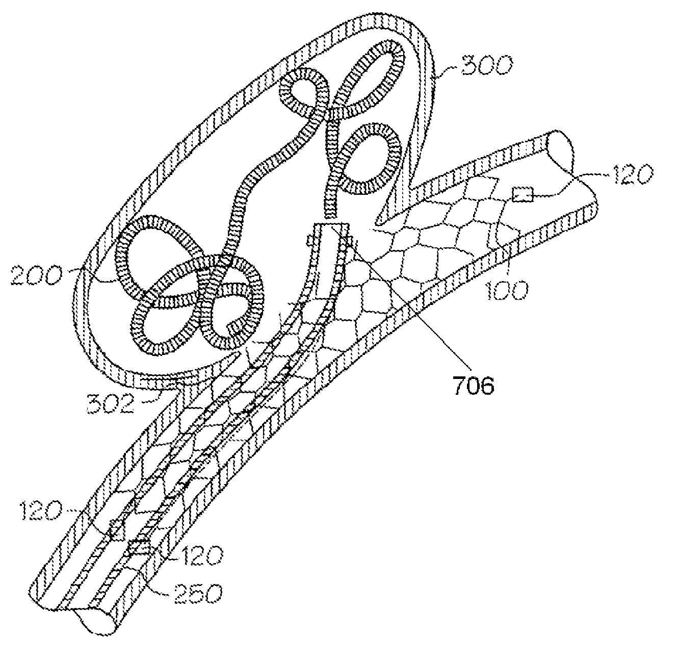
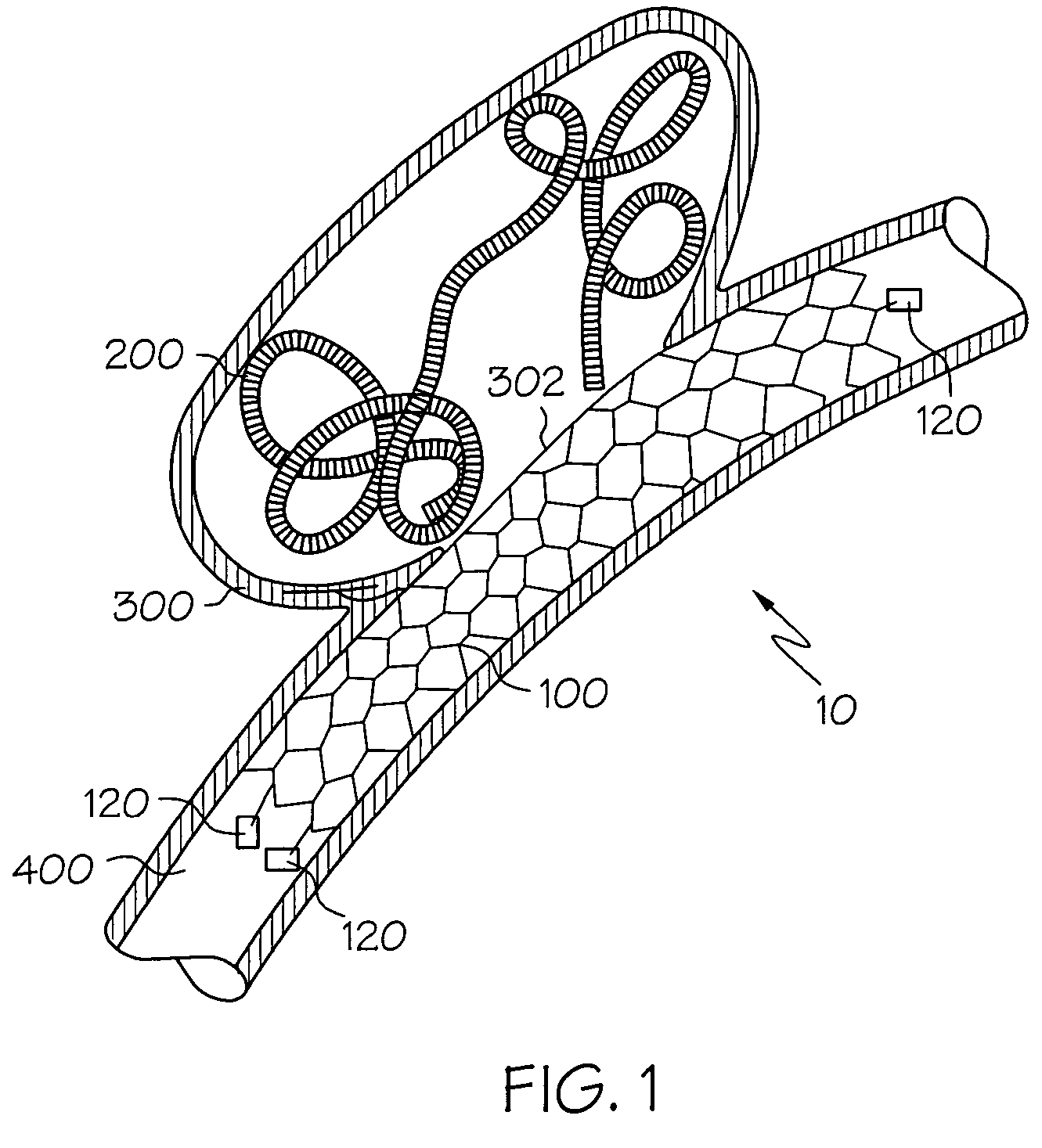
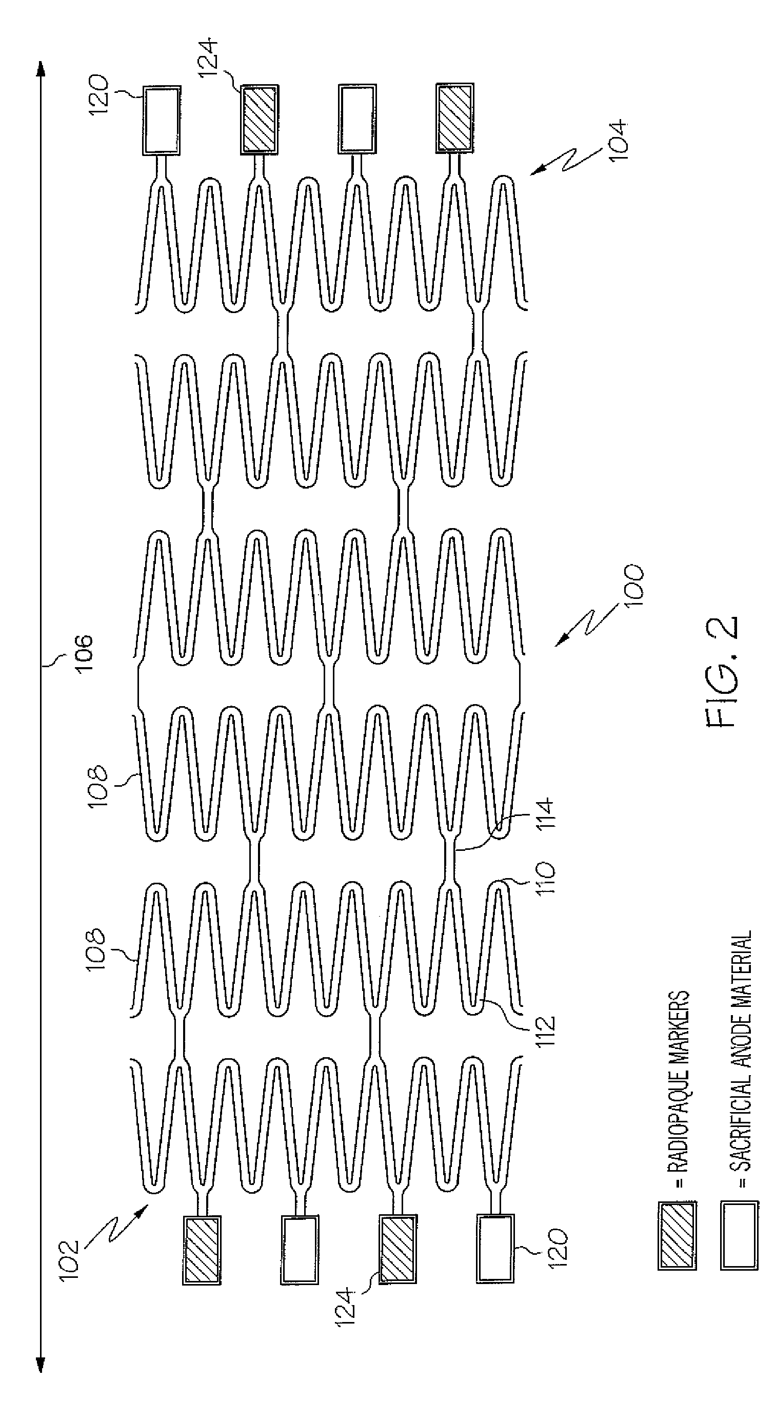
The sacrificial anode stent system 10 generally includes a vascular support structure in the form of a stent 100. Non-limiting examples of stent which may be used in the instant invention are disclosed in U.S. patent application Ser. No. 09 / 957,983 which is incorporated herein by reference in its entirety. The sacrificial anode stent system 10 also generally utilizes a vaso-occlusive device such as a platinum coil 200 for positioning in a wide-neck aneurysm 300 as more fully described in U.S. Pat. Nos. 5,423,829; 5,643,254; 6,059,779; a...


PUM


Abstract

A sacrificial anode stent system comprises a stent having at least one sacrificial anode portion and a vaso-occlusive device. The vaso-occlusive device has at least one portion with a potential different from that of the sacrificial anode portion of the stent.

Description

FIELD OF THE INVENTIONThe present invention relates generally to implantable devices and methods for the non-invasive treatment of vascular defects such as an aneurysm.BACKGROUND OF THE INVENTIONAn aneurysm may generally be described as a weakening in the wall of an artery or vein resulting in a bulge or bubble protruding in a radial direction relative to the adjacent vessel wall.In the past, aneurysms have been treated through a procedure which surgically clips an aneurysm shut with a metal clip. Alternatively, the neck of the aneurysm may be clipped followed by a suture ligation of the neck of the aneurysm or the wrapping of the entire aneurysm. Each of these surgical procedures constitutes an intrusive invasion into the body for which certain areas of the body such as the brain have little tolerance. An aneurysm left untreated may rupture and hemorrhage resulting in a hemorrhagic stroke.In the past, it has been very difficult to treat a patient having a high risk wide-neck brain ...

Claims


Application Information

Patent Timeline
Patent Type & Authority Patents(United States)
IPC IPC(8): A61M29/00A61F2/82A61B17/12A61F2/00
CPCA61B17/12022A61B17/12118A61B17/1214A61F2/91A61F2/915A61B17/12036A61F2220/0058A61B2017/12063A61F2002/3008A61F2002/823A61F2002/91541A61F2002/91558A61F2250/0054A61F2250/0098Y10S623/903A61F2220/0041A61F2220/005
Inventor GRIFFEN, STEPHENGERBERDING, BRENT C.
Owner BOSTON SCI SCIMED INC
Why Eureka
Try Eureka