Method and apparatus for emission guided radiation therapy

a radiation therapy and radiation therapy technology, applied in the field of radiation therapy apparatus and method, can solve the problems of limiting the effectiveness of external beam rt, static errors arise from patient setup variability, and dynamic errors arise from tumor motion

Active Publication Date: 2011-09-13
REFLEXION MEDICAL INC
View PDF28 Cites 46 Cited by
  • Summary
  • Abstract
  • Description
  • Claims
  • Application Information

AI Technical Summary

Benefits of technology

The present subject matter relates to apparatus and method for scanning and aligning radiation along coincident positron annihilation emission paths. A method includes detecting a coincident positron annihilation emission path from a radioactive event intersecting a predetermined volume during a session, and aligning a radiation source along the emission path during the session. Various examples include repeated, timely alignment of radiation in response to individual detected emission events. Various examples include receiving location data to identify predetermined volumes and avoid directing radiation to radiation sensitive areas.

Problems solved by technology

However, uncertainty associated with tumor location and motion can limit effectiveness of external beam RT.
Static errors arise from patient setup variability as well as natural changes in the tumor location due to shifting of the internal organs.
Dynamic errors arise from tumor motion during treatment (e.g. due to patient breathing).
IGRT techniques, however, suffer either from a lack of specificity of the tumor imaging (e.g. in many cases it is nearly impossible to visualize the tumor boundaries from x-ray CT), or from poor temporal resolution (PET is the most sensitive modality to imaging cancer however it take minutes to form a good quality PET image).
In either case, it is still very difficult to dynamically track a tumor during RT.
However, it is impractical to use PET simultaneously with external beam RT.
PET imaging takes on the order of 10 minutes to acquire an image of reasonable quality which severely limits the use of PET as an agent for dynamic tracking of tumor position.

Method used


Image

  • Method and apparatus for emission guided radiation therapy
  • Method and apparatus for emission guided radiation therapy
  • Method and apparatus for emission guided radiation therapy

Examples


Embodiment Construction

The following detailed description of the present invention refers to subject matter in the accompanying drawings which show, by way of illustration, specific aspects and embodiments in which the present subject matter may be practiced. These embodiments are described in sufficient detail to enable those skilled in the art to practice the present subject matter. References to “an”, “one”, or “various” embodiments in this disclosure are not necessarily to the same embodiment, and such references contemplate more than one embodiment. The following detailed description is, therefore, not to be taken in a limiting sense, and the scope is defined only by the appended claims, along with the full scope of legal equivalents to which such claims are entitled.

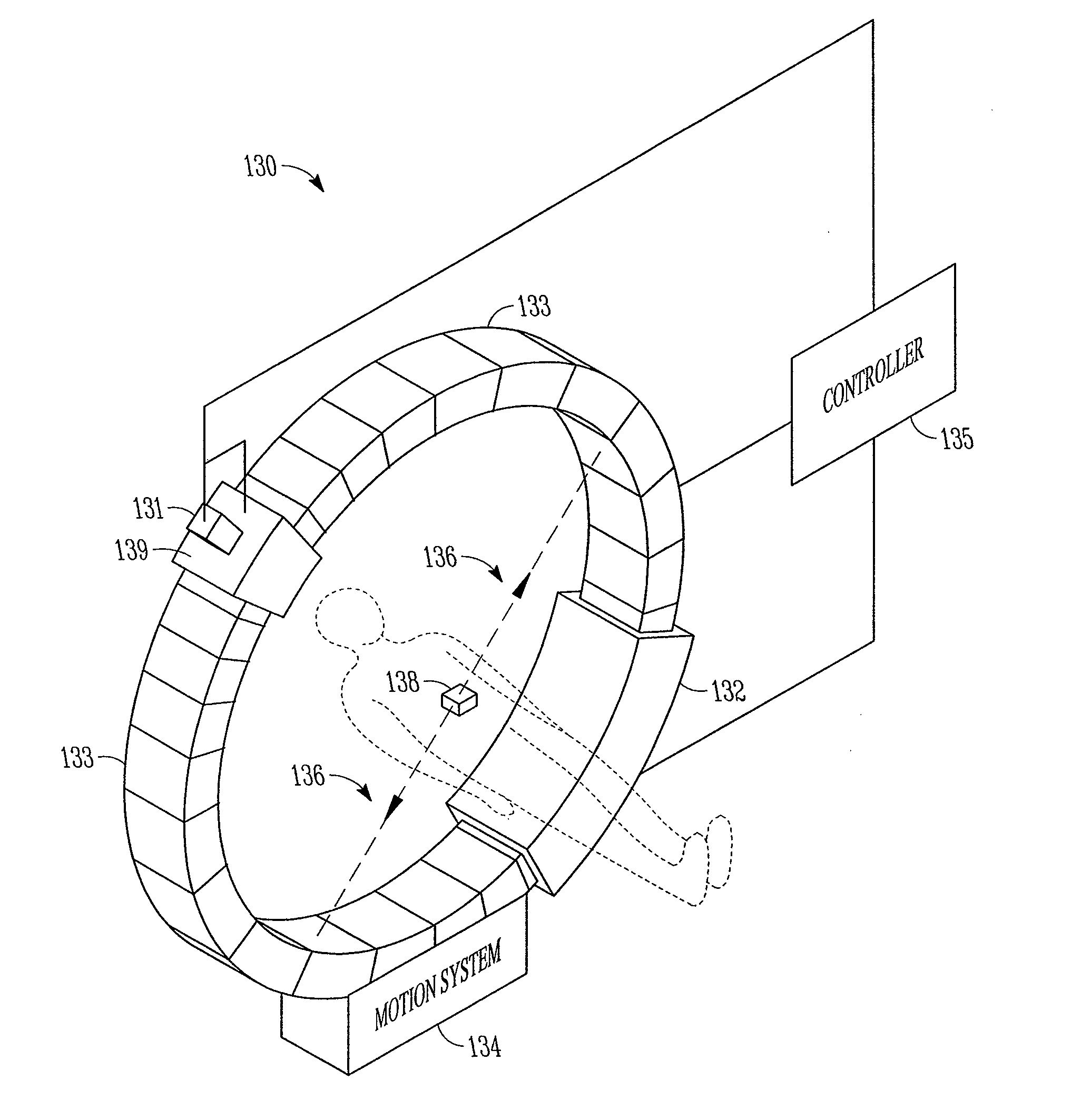
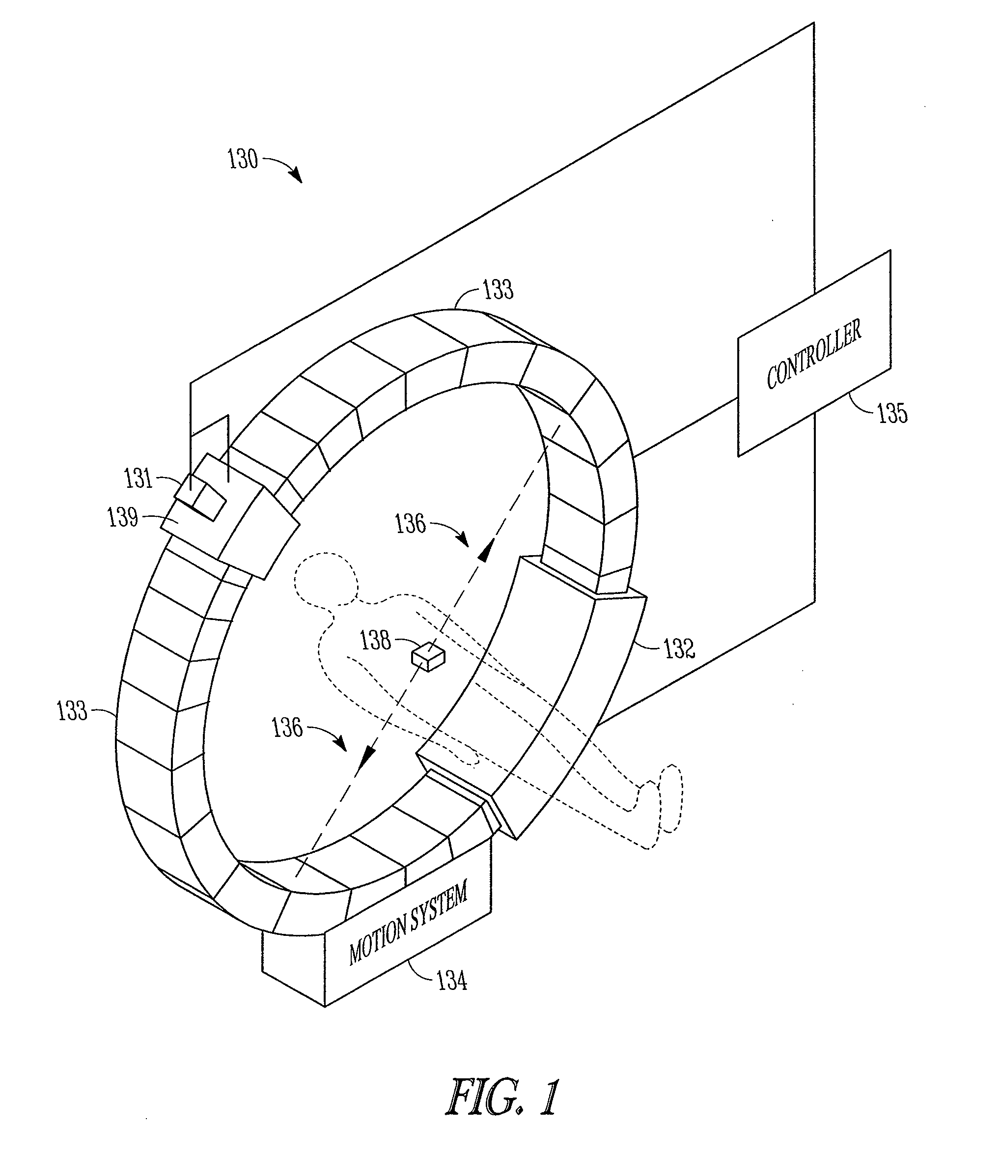
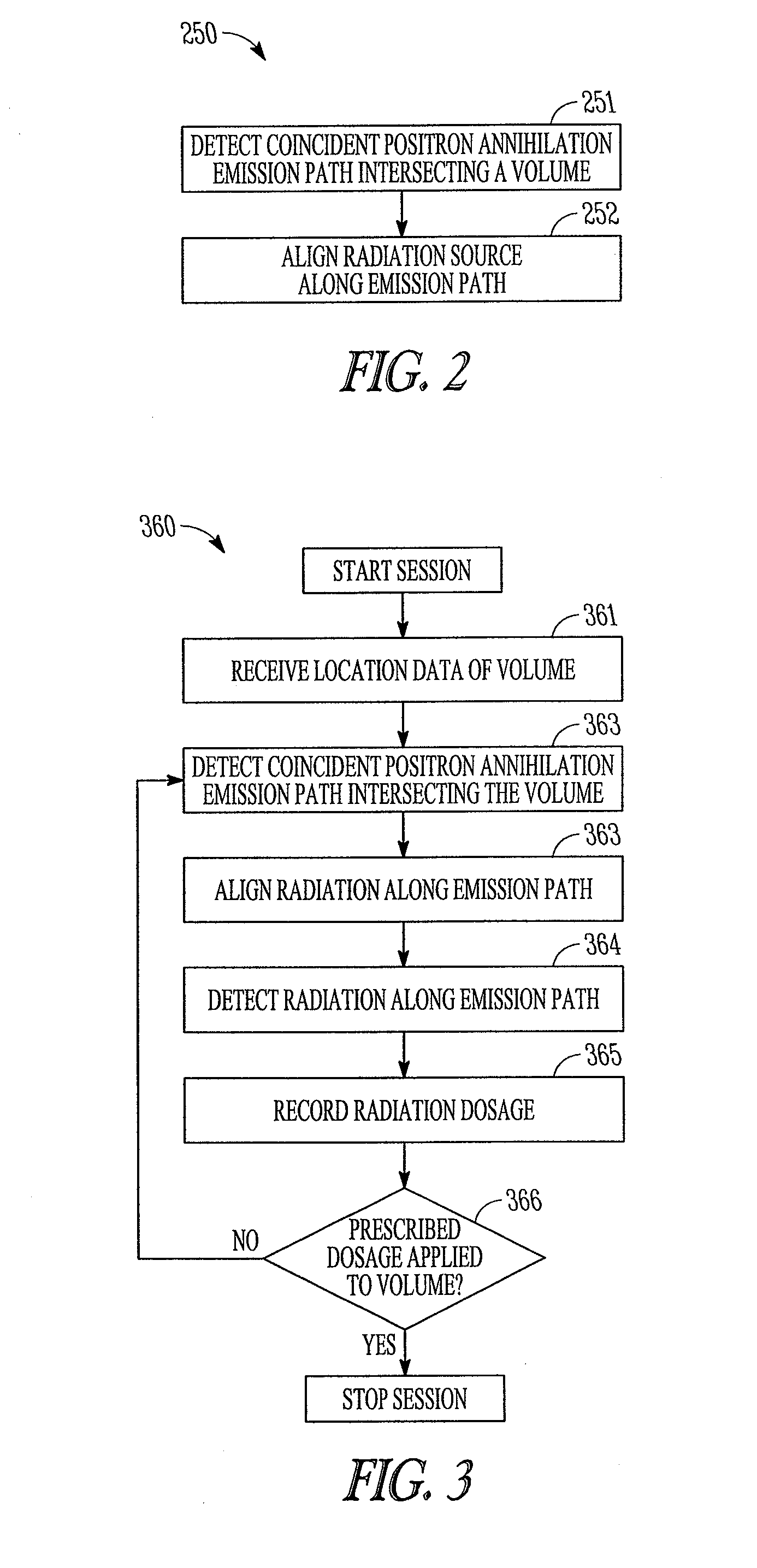
The present subject matter relates to a new class of techniques termed emission guided radiation therapy (“EGRT”). One EGRT method includes using an emission modality that is highly sensitive to cancer directly during the treatment stage...


PUM


Abstract

An apparatus comprising a radiation source, coincident positron emission detectors configured to detect coincident positron annihilation emissions originating within a coordinate system, and a controller coupled to the radiation source and the coincident positron emission detectors, the controller configured to identify coincident positron annihilation emission paths intersecting one or more volumes in the coordinate system and align the radiation source along an identified coincident positron annihilation emission path.

Description

FIELD OF TECHNOLOGYThis disclosure relates to apparatus and method for radiation therapy and more particularly to apparatus and method for treating cancer tissue in the body using high energy radiation.BACKGROUNDRadiation therapy (RT) is a method for treating cancerous tissue in the body using high energy radiation (e.g. x-rays) to kill tumor cells. There are two main types of RT: internal beam and external beam. Internal beam RT is achieved by implanting radioactive material within the patient inside or near the cancerous site to be treated. External beam RT is achieved by aiming a high energy beam of radiation through the patient so that it passes through the region to be treated. External RT has evolved significantly over the past few decades. In an effort to apply a lethal radiation dose to a tumor while sparing healthy tissue, techniques such as three-dimensional conformal beam RT are used to shape the beam to match the two-dimensional projection of the tumor onto the patient s...

Claims


Application Information

Patent Timeline
Patent Type & Authority Patents(United States)
IPC IPC(8): G01T1/166
CPCG01T1/2985A61B6/54A61N5/1067A61B6/037G01T1/2978A61N5/1081A61N2005/1074A61B6/0407A61B6/469A61B6/541A61N2005/1052A61N2005/1072A61N2005/1087A61N2005/1089A61N2005/109A61N2005/1091
Inventor MAZIN, SAMUEL
Owner REFLEXION MEDICAL INC
Why Eureka
Try Eureka