Buck-boost regulator

a buck converter and regulator technology, applied in the direction of power conversion systems, dc-dc conversion, instruments, etc., can solve the problems of buck converters reducing a higher input voltage to a lower output voltage but generally not applicable, buck converters incur efficiency or component count and/or component size penalties,

Active Publication Date: 2011-09-13
INTERSIL INC
View PDF59 Cites 68 Cited by
  • Summary
  • Abstract
  • Description
  • Claims
  • Application Information

AI Technical Summary

Benefits of technology

[0007]In one embodiment, the buck and boost window voltages are adjusted based on the input voltage. In a more specific embodiment, the window voltages are adjusted based a difference between the input and output voltages.

Problems solved by technology

A boost converter can boost voltage of a lower input voltage but is generally not applicable when the input voltage is higher than the output voltage.
A buck converter reduces a higher input voltage to a lower output voltage but is generally not applicable when the input voltage is lower than the desired output voltage.
Both of these solutions incur efficiency or component count and / or component size penalties.
Controlling the H-Bridge switches in this arrangement, however, is difficult when attempting to achieve both high efficiency and low output ripple, especially in the region of operation in which the output voltage and the input voltage values are very close.

Method used


Image

  • Buck-boost regulator
  • Buck-boost regulator
  • Buck-boost regulator

Examples


Embodiment Construction

[0015]The following description is presented to enable one of ordinary skill in the art to make and use the present invention as provided within the context of a particular application and its requirements. Various modifications to the preferred embodiment will, however, be apparent to one skilled in the art, and the general principles defined herein may be applied to other embodiments. Therefore, the present invention is not intended to be limited to the particular embodiments shown and described herein, but is to be accorded the widest scope consistent with the principles and novel features herein disclosed.

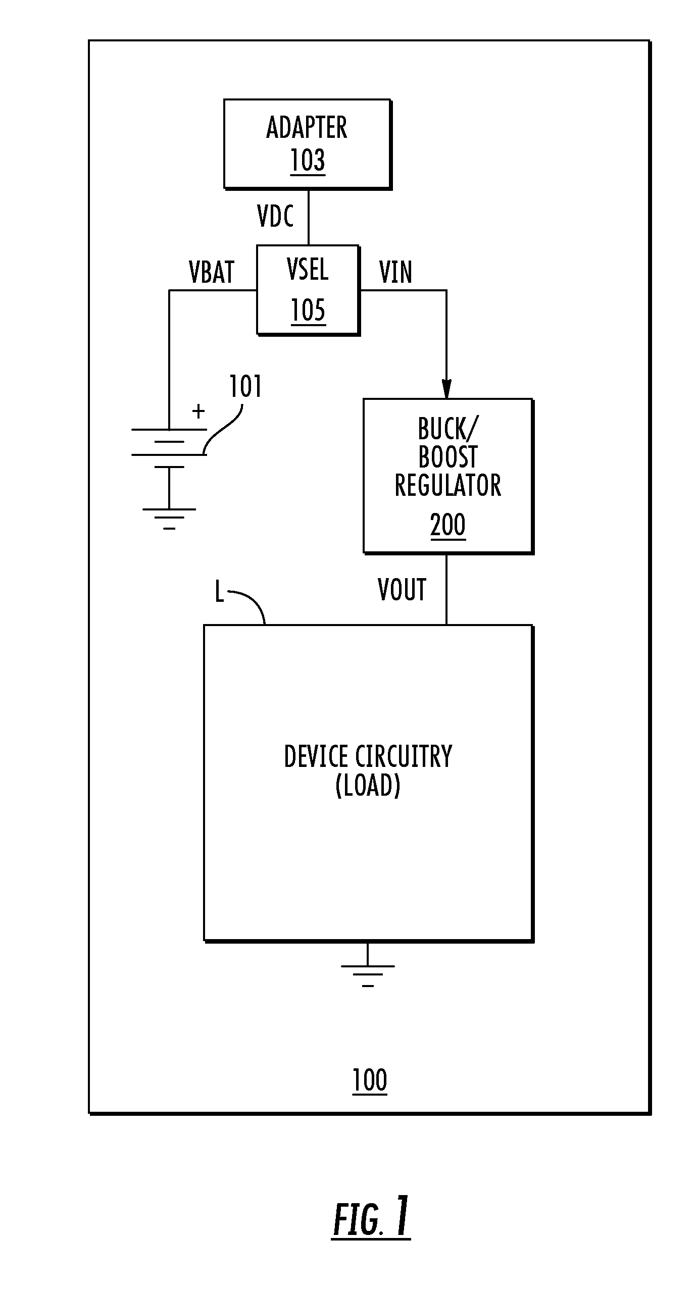
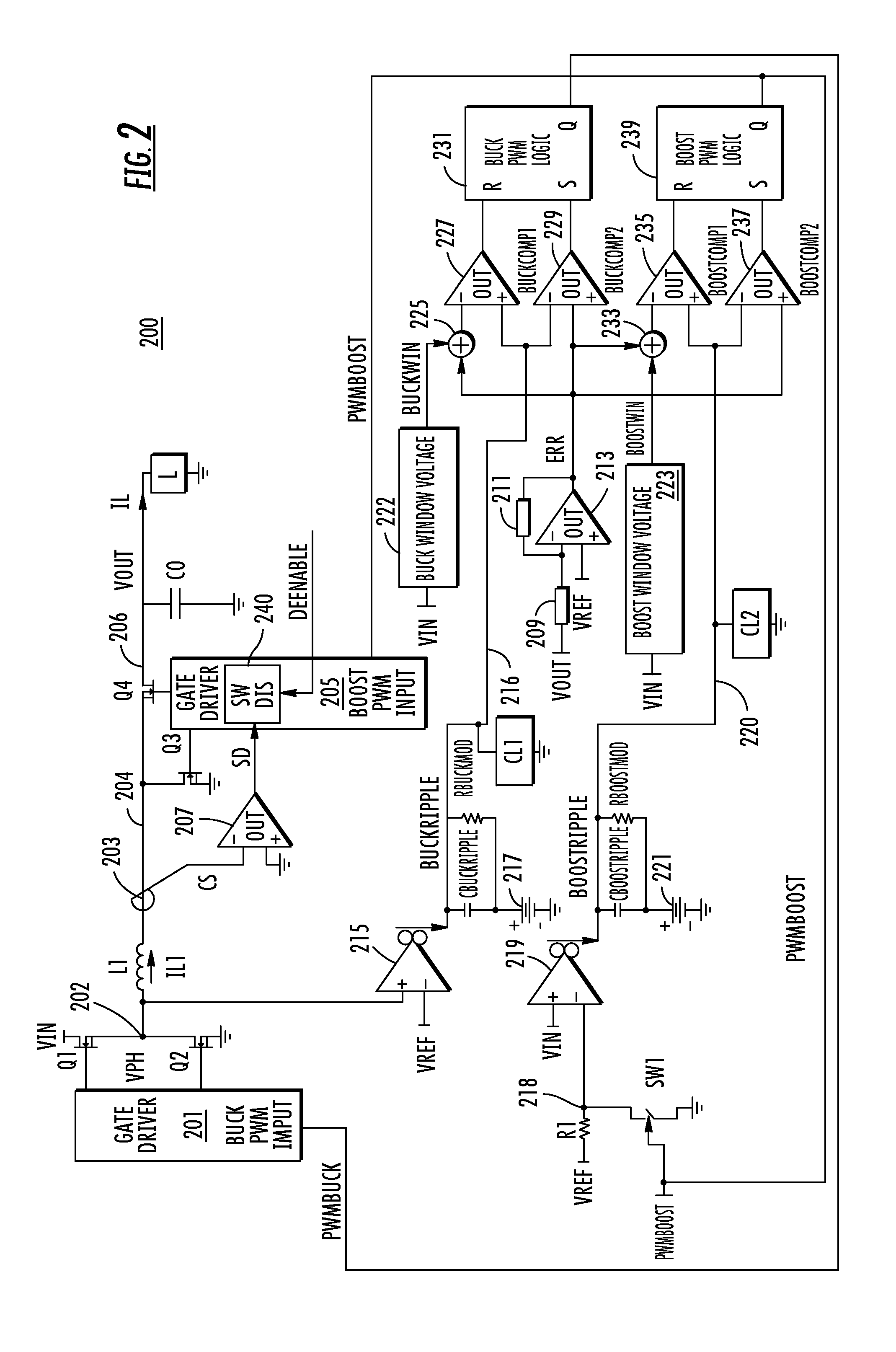
[0016]The present disclosure describes a system and method of controlling the buck and boost regulator switches in an H-bridge configuration using synthetic ripple regulation, although alternative configurations are possible. The system and method includes operation in both discontinuous conduction mode (DCM) and continuous conduction mode (CCM) states. In the illustrated embod...


PUM


Abstract

A buck-boost regulator for converting an input voltage to an output voltage which includes an inductor, an error circuit providing an error voltage, buck and boost switching circuits, buck and boost ripple circuits, and buck and boost hysteretic comparator circuits. The buck switching circuit switches a first end of the inductor, the buck ripple circuit replicates ripple current through the inductor based on the buck pulse signal and provides a buck ripple voltage, and the buck hysteretic comparator circuit develops the buck pulse signal based on a buck window voltage range using the error voltage. The boost switching circuit switches a second end of the inductor, the boost ripple circuit replicates ripple current through the inductor based on the boost pulse signal and provides a boost ripple voltage, and the boost hysteretic comparator circuit develops the boost pulse signal based on a boost window voltage range using the error voltage.

Description

CROSS-REFERENCE TO RELATED APPLICATIONS[0001]This application claims the benefit of U.S. Provisional Application Ser. No. 60 / 957,838, filed on Aug. 24, 2007, which is herein incorporated by reference for all intents and purposes. This application is also related to application entitled “BOOST REGULATOR USING SYNTHETIC RIPPLE REGULATION” filed concurrently herewith at least one common inventor and which is commonly assigned, which is herein incorporated by reference for all intents and purposes.DESCRIPTION OF THE RELATED ART[0002]Many electronic devices require voltage rails that fall both above and below the input voltage range of the device. The very common 5 Volt (V) and / or 3.3V rails in systems often have this situation when required to run from battery source and an alternating current (AC) adaptor source. A boost converter can boost voltage of a lower input voltage but is generally not applicable when the input voltage is higher than the output voltage. A buck converter reduces...

Claims


Application Information

Patent Timeline
Patent Type & Authority Patents(United States)
IPC IPC(8): G05F1/24
CPCH02M3/1582H02M2001/0003H02M1/0003
Inventor PETRICEK, SHEA LYNN
Owner INTERSIL INC
Why Eureka
Try Eureka