Imaging optical system for image sensor

an image sensor and optical system technology, applied in the field of image sensor imaging optical system, can solve the problems of chromatic aberration, ir cut-off filter disadvantages in light transmittance, and dramatic changes in the spectral characteristics of an image formed, and achieve the effect of small size and low chromatic aberration

Inactive Publication Date: 2011-09-13
COMPACT LENS TECH LLC
View PDF6 Cites 28 Cited by
  • Summary
  • Abstract
  • Description
  • Claims
  • Application Information

AI Technical Summary

Benefits of technology

[0009]The present invention provides an imaging optical system having a small size and low chromatic aberration.

Problems solved by technology

Unfortunately, when this kind of IR cut-off filter is combined with a lens, the spectral characteristics of an image formed changes dramatically according to the angle at which light is incident to the lens and filter combination.
IR cut-off filters thus present disadvantages in terms of light transmittance.
Chromatic aberration presents another problem for a conventional lens and IR cut-off filter combination.
Since there are differences between the transmittances and the spectral characteristics of a center portion of the filter and lens combination and a peripheral portion of the filter and lens combination, large chromatic aberrations are generated.
In addition, Moire patterns tend to form on conventional IR cut-off filters, further degrading image quality.
These disadvantages are compounded by the difficulty of manufacturing a lens and IR cut-off filter using lower cost reflow processes.
Demands for developing reflowable camera modules have continuously increased, but the conventional lens and IR cut-off filter combination remains difficult to make in a reflow process.

Method used


Image

  • Imaging optical system for image sensor
  • Imaging optical system for image sensor
  • Imaging optical system for image sensor

Examples


first embodiment

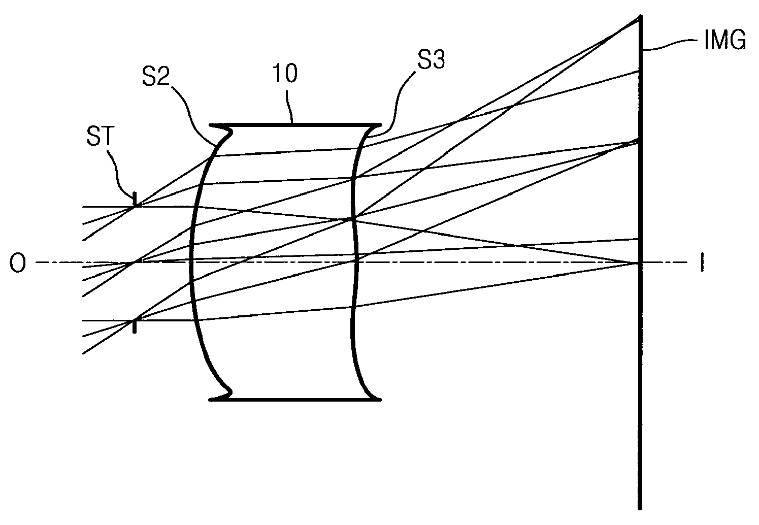
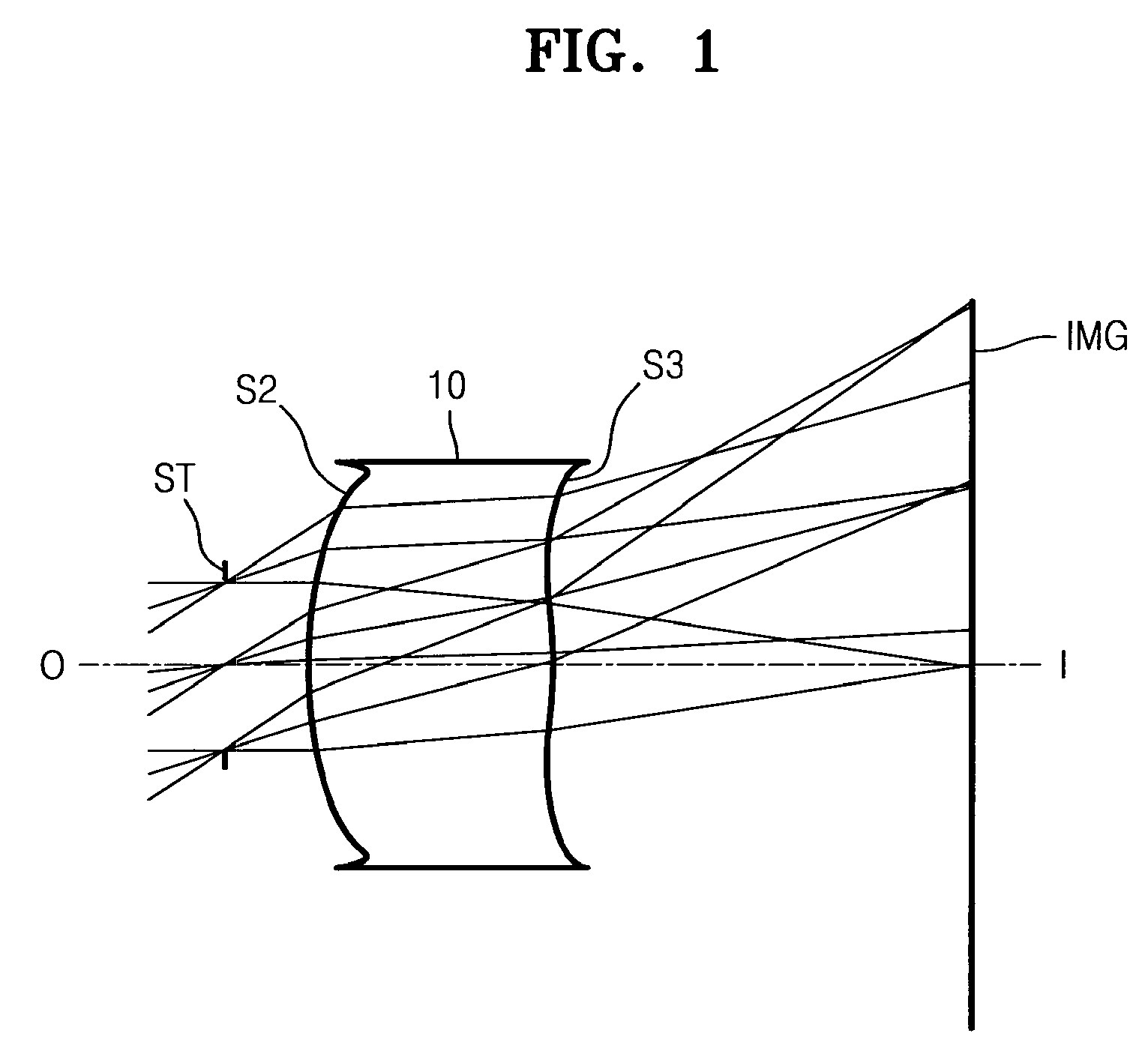
[0063]FIG. 1 shows a imaging optical system according to the first embodiment.

[0064]

f: 1.26 Fno: 3.2 ω: 32.56RDnndvdOBJ: INFINITYINFINITYST: INFINITY0.195000S2: 1.000000.5600001.63350.3ASP:K: 2.191907A: 0.643524E+00B: 0.117310E+02C: −.447364E+03D: 0.490994E+04E: −.546912E+04F: −.266199E+06G: 0.144047E+07H: 0.787653E+06J: −.125880E+08S3: −3.155790.299811ASP:K: −4045.049088A: −.125363E+01B: 0.420788E+02C: −.339024E+03D: 0.828909E+03E: 0.467456E+04F: −.831814E+04G: −.178741E+06H: 0.544354E+06J: 0.317769E+06S4: INFINITY0.300017S5: INFINITY0.385735IMG: INFINITY0.000000

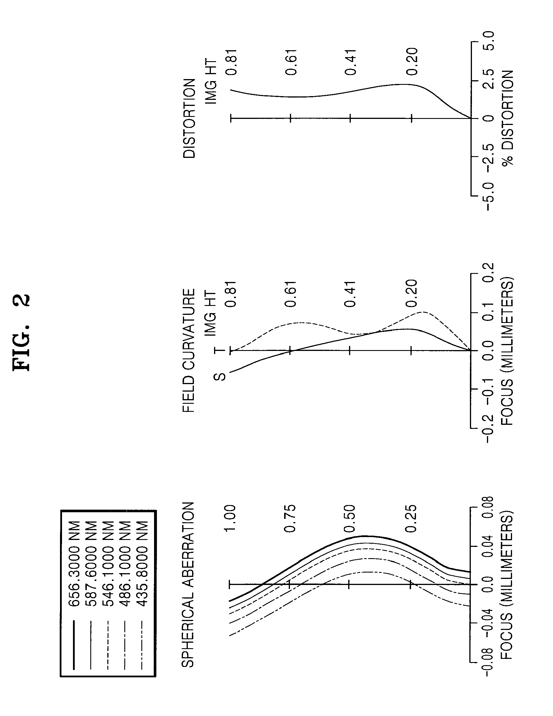
[0065]In above data, S4 and S5 denote air gaps. FIG. 2 shows a spherical aberration, a field curvature, and a distortion of the imaging optical system according to the first embodiment of the present invention. The spherical aberration is measured with respect to C_line, e-line, and F-line. C_line is 656.3 nm, e-line is 546 nm, and F-line is 486.1 nm. As the field curvature, a tangential field curvature (T) and a sagittal f...

second embodiment

[0066]FIG. 3 shows a imaging optical system according to a second embodiment of the present invention.

[0067]

f: 1.26 Fno: 3.2 ω: 32.63RDnndvdOB: INFINITYINFINITYST: INFINITY0.195000S2: 1.003570.6389521.63350.3ASP:K: −0.532900A: 0.107903E+00B: 0.296528E+02C: −.679410E+03D: 0.629045E+04E: −.285691E+04F: −.324820E+06G: 0.145024E+07H: 0.178514E+07J: −.125880E+08S3: −3.114270.299792ASP:K: −2626.799076A: −.194333E+01B: 0.474362E+02C: −.366073E+03D: 0.904787E+03E: 0.348703E+04F: −.682097E+04G: −.127166E+06H: 0.493206E+06J: −.391541E+06S4: INFINITY0.299998S5: INFINITY0.355876IMG: INFINITY0.000000

[0068]FIG. 4 shows a spherical aberration, a field curvature, and a distortion aberration of the imaging optical system according to the second embodiment of the present invention.

third embodiment

[0069]FIG. 5 shows a imaging optical system according to a third embodiment of the present invention.

[0070]

f: 1.27 Fno: 3.2 ω: 32.66RDnndvdOB: INFINITYINFINITYST: INFINITY0.195000S2: 0.930000.5000001.63350.3ASP:K: 1.663684A: −.746585E−01B: 0.328027E+02C: −.710407E+03D: 0.599582E+04E: 0.431900E+03F: −.326557E+06G: 0.157794E+07H: 0.604628E+06J: −.125880E+08S3: −5.165640.299799ASP:K: −15564.71781A: −.663127E+00B: 0.395772E+02C: −.323673E+03D: 0.715367E+03E: 0.436288E+04F: 0.347210E+03G: −.152467E+06H: −.484282E+05J: 0.199846E+07S4: INFINITY0.300006S5: INFINITY0.412668IMG: INFINITY0.000000

[0071]FIG. 6 a spherical aberration, a field curvature, and a distortion aberration of the imaging optical system according to the third embodiment of the present invention.


PUM


Abstract

Provided is a imaging optical system for an image sensor. The imaging optical system includes a stop and a first lens sequentially arranged from an object side. The first lens has aspherical surfaces on both sides and has a positive refractive power, a first surface of the first lens which faces the object side is a convex surface and a second surface of the first lens which faces an image side is a convex surface.

Description

CROSS-REFERENCE TO RELATED PATENT APPLICATIONS[0001]This application claims the benefit of Korean Patent Application No. 10-2008-0044025, filed on May 13, 2008, and Korean Patent Application No. 10-2008-0082370, filed on Aug. 22, 2008, in the Korean Intellectual Property Office, the disclosures of which are incorporated herein by reference.BACKGROUND OF THE INVENTION[0002]1. Field of the Invention[0003]The present invention relates to a small, light, and inexpensive imaging optical system for an image sensor.[0004]2. Description of the Related Art[0005]Recently, the use of digital cameras or video cameras including a solid state pickup device such as a charge coupled device (CCD) or a complementary metal-oxide semiconductor (CMOS) has considerably increased. In particular, camera modules offering high megapixel resolution are required in many applications. Manufacturers are always searching for ways to make smaller and lighter digital cameras that can be manufactured at law cost. Th...

Claims


Application Information

Patent Timeline
Patent Type & Authority Patents(United States)
IPC IPC(8): H04N5/225G02B13/18
CPCG02B3/04G02B13/0025
Inventor CHOI, BYUNG-HA
Owner COMPACT LENS TECH LLC
Why Eureka
Try Eureka