Over-current protection for a power converter

a power converter and overcurrent protection technology, applied in the field of power converters, can solve the problems of large input and output capacitors, current ratcheting may occur in switching regulators, and “ratcheting” of inductor current to very high levels

Active Publication Date: 2011-09-13
SEMICON COMPONENTS IND LLC
View PDF79 Cites 59 Cited by
  • Summary
  • Abstract
  • Description
  • Claims
  • Application Information

AI Technical Summary

Benefits of technology

[0010]According to still yet another embodiment of the present invention, circuitry provides protection against a short circuit in a power converter system. The power converter system has one or more transistors which can be switched on and off at a primary frequency to cause current to flow through an inductor in an amount up to a primary current limit. The circuitry includes an overcurrent protection circuit operable to monitor a voltage at a compensation node, wherein the voltage at the compensation node is indicati...

Problems solved by technology

Current ratcheting may occur in switching regulators using current mode control because the control loop takes a finite time to react.
This process, which continues at the rate of the switching frequency, causes a “ratcheting” of the inductor current to very high levels—sometimes with catastrophic outcomes, such as a complete breakdown of the switching regulator.
As such...

Method used


Image

  • Over-current protection for a power converter
  • Over-current protection for a power converter
  • Over-current protection for a power converter

Examples


Embodiment Construction

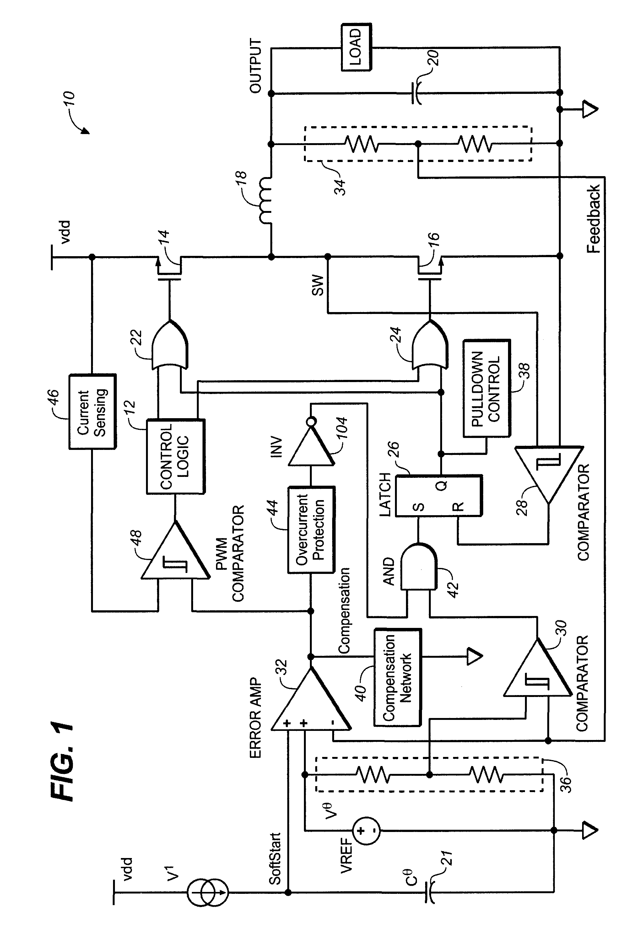
[0017]Embodiments of the present invention and their advantages are best understood by referring to FIGS. 1 through 4 of the drawings. Like numerals are used for like and corresponding parts of the various drawings.

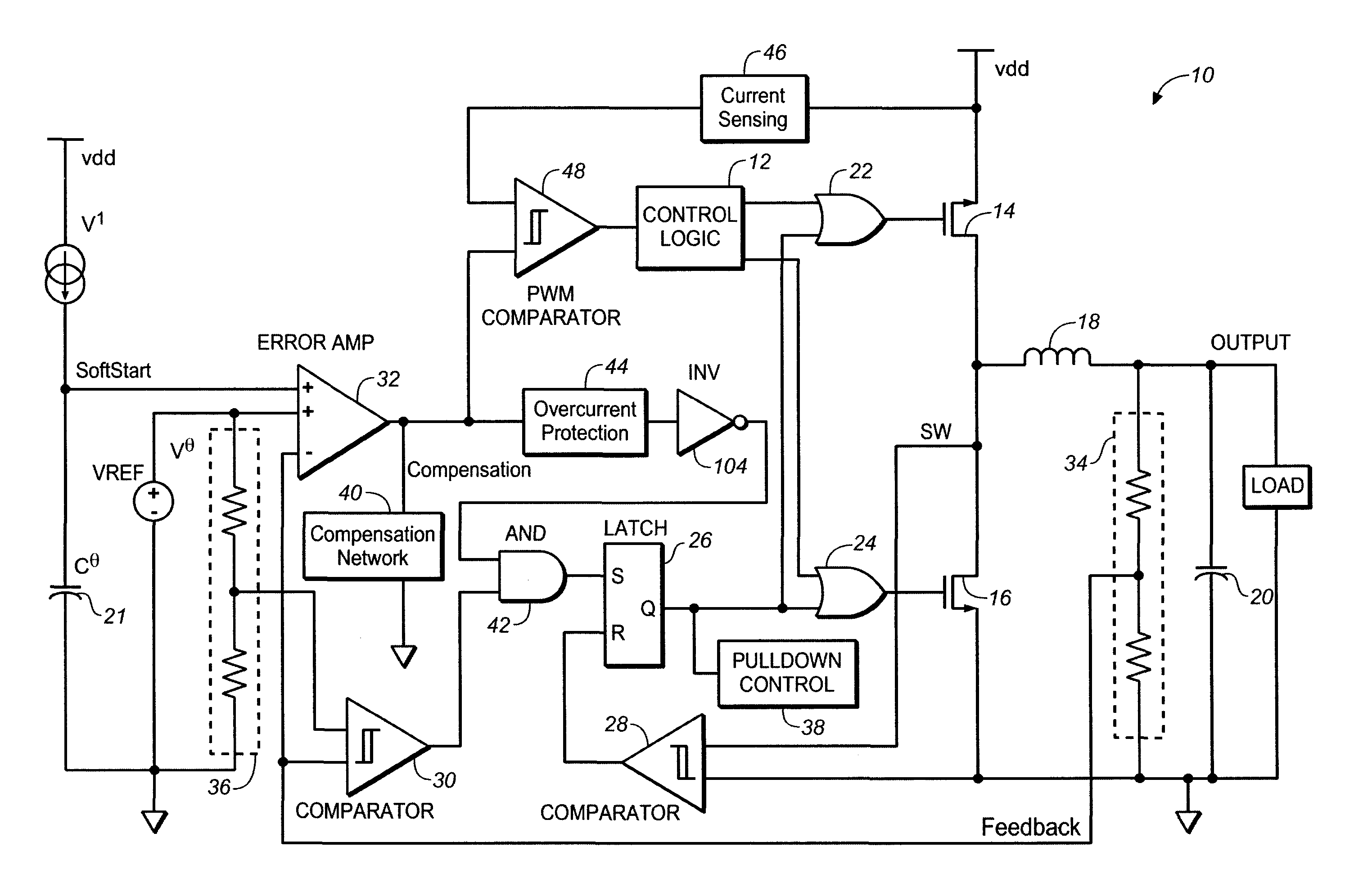
[0018]In various embodiments, the present invention provides systems, circuitry, and methods for protection against catastrophic failures due to current ratcheting in a power converter system (which is a systemic problem of current mode control due to finite loop speed). The systems, circuitry, and methods may provide over-current or short circuit protection using the primary current limit of a power converter system (e.g., switching regulator) and normal switching frequency.

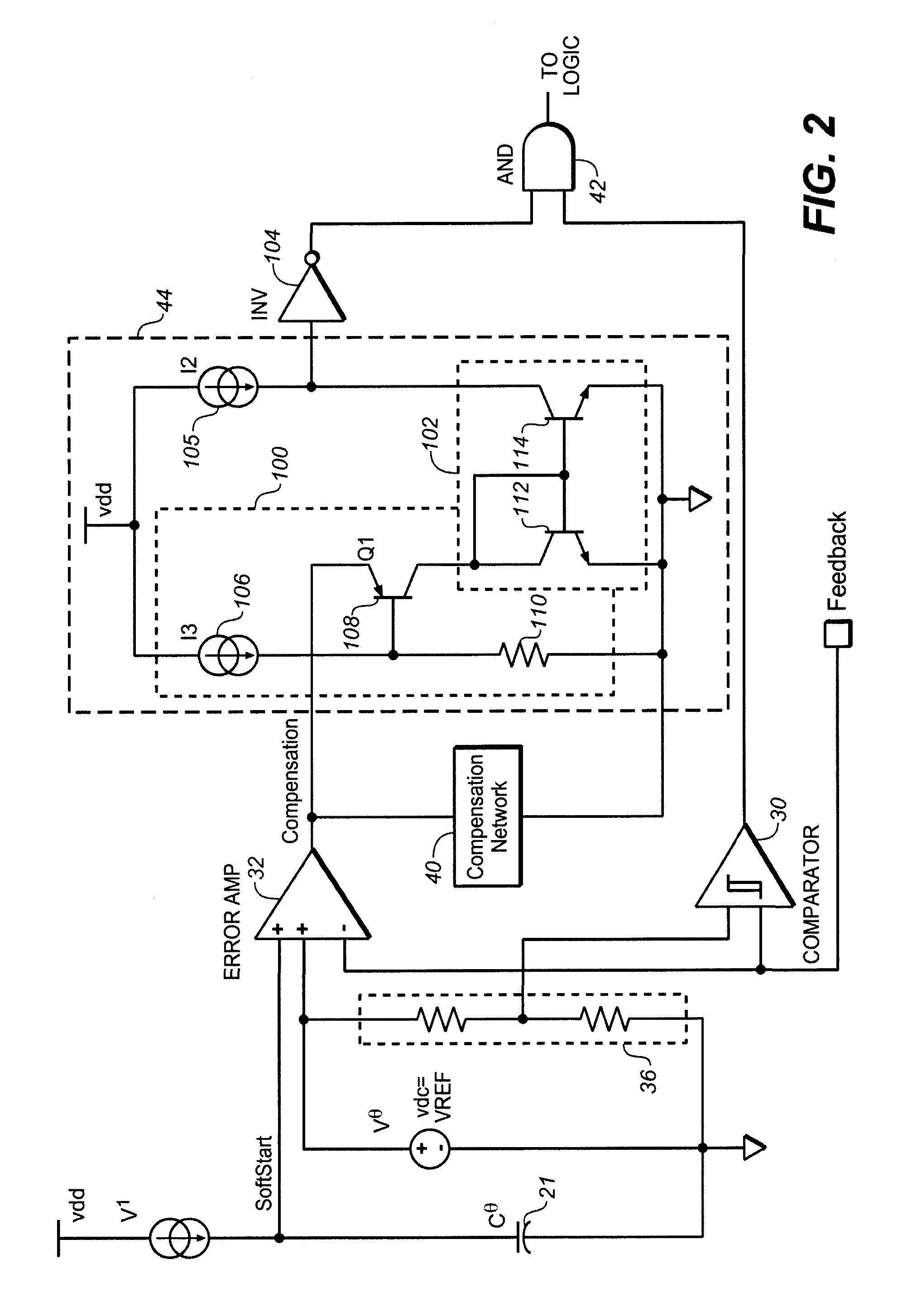
[0019]In one embodiment, a clamp circuit provided at the error signal of a current mode DC / DC voltage regulator dictates or sets the maximum current that can be sourced at the output. Once the clamp is activated, the maximum current at the load has been met. If the clamp is activated at a point where ...


PUM


Abstract

In one embodiment, a method is provided for a power converter system. The method includes: providing a primary current limit for the power converter system, wherein the power converter system has one or more transistors which can be switched on at a primary frequency to cause current to flow through an inductor of the power converter system; and using the primary current limit for over-current protection in the power converter system, wherein over-current protection does not employ any secondary frequency for switching of the one or more transistors and does not employ any secondary current limit.

Description

BACKGROUND[0001]1. Field of Invention[0002]The present invention relates to power converters, and more particularly to, to over-current protection for a power converter.[0003]2. Description of Related Art[0004]Power converters are essential for many modern electronic devices. Among other capabilities, power converters can adjust voltage level downward (buck converter) or adjust voltage level upward (boost converter). Power converters may also convert from alternating current (AC) power to direct current (DC) power, or vice versa. Power converters are typically implemented using one or more switching devices, such as transistors, which are turned on and off to deliver power to the output of the converter. Control circuitry is provided to regulate the turning on and off of the switching devices, and thus, these converters are known as “switching regulators” or “switching converters.” The power converters may also include one or more capacitors or inductors for alternately storing and ...

Claims


Application Information

Patent Timeline
IPC IPC(8): H02H7/00
CPCH02M1/32H02M3/1588Y02B70/1466Y02B70/10
Inventor WU, ANDREW
Owner SEMICON COMPONENTS IND LLC
Why Eureka
Try Eureka