

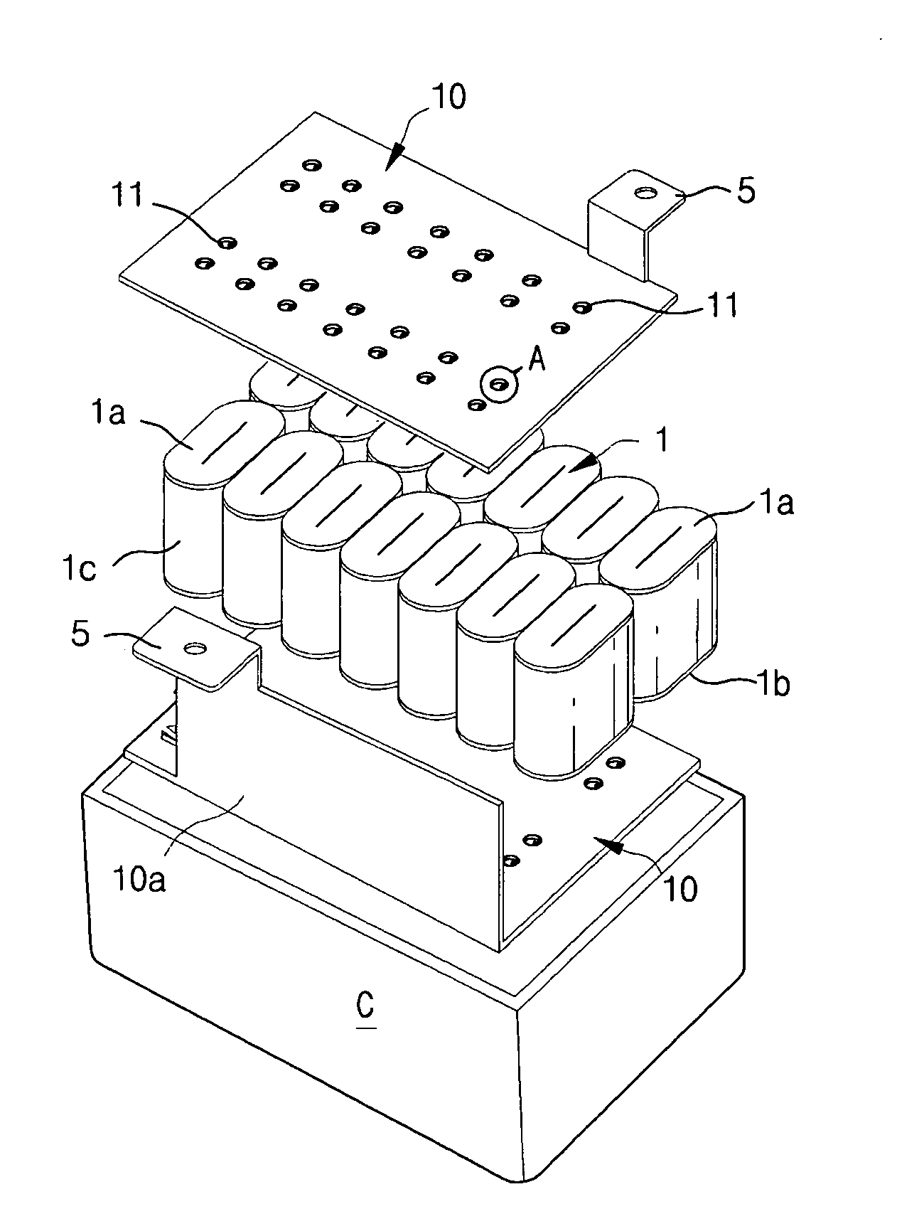
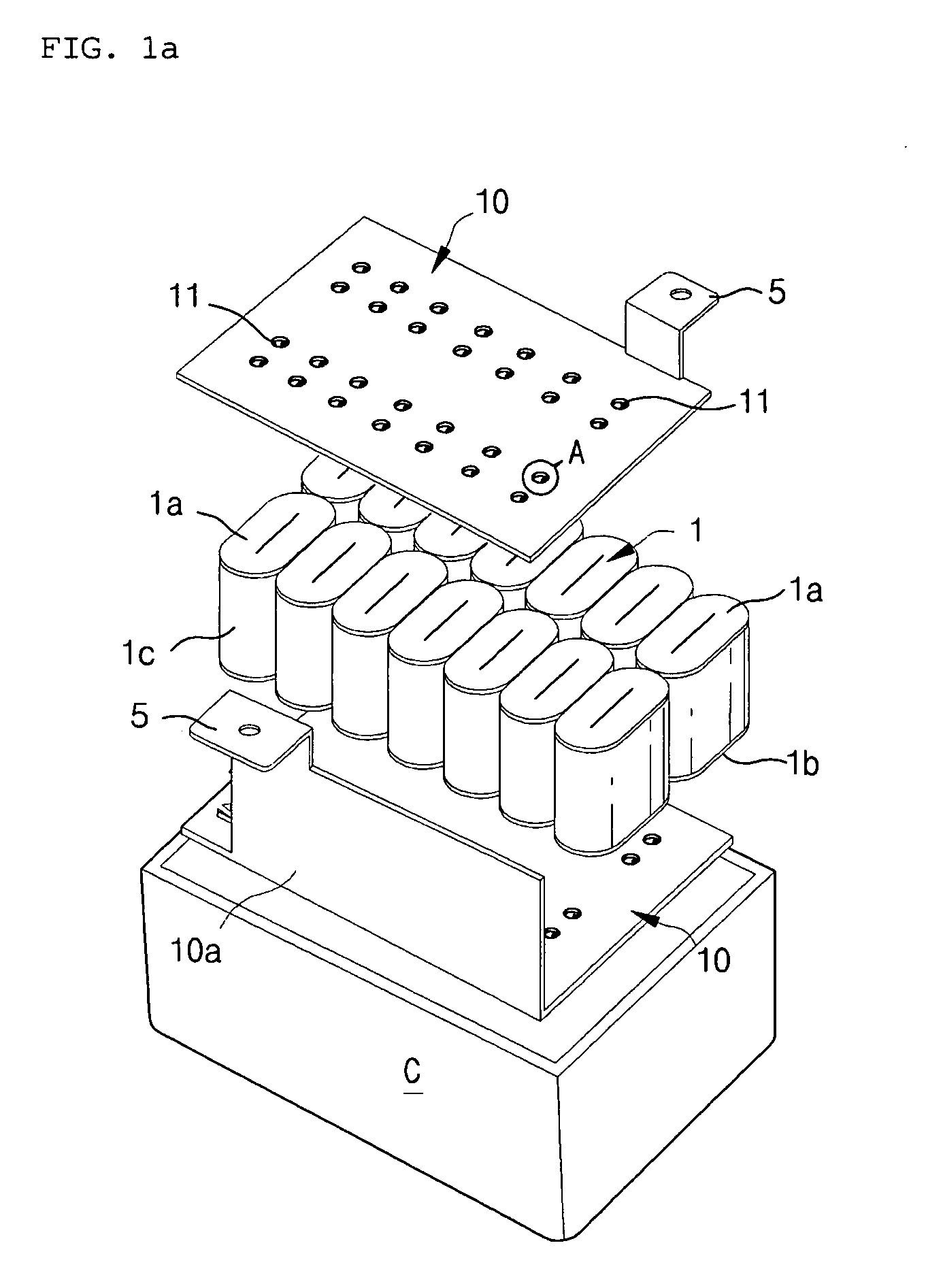
Bus-bar for jointing capacitor
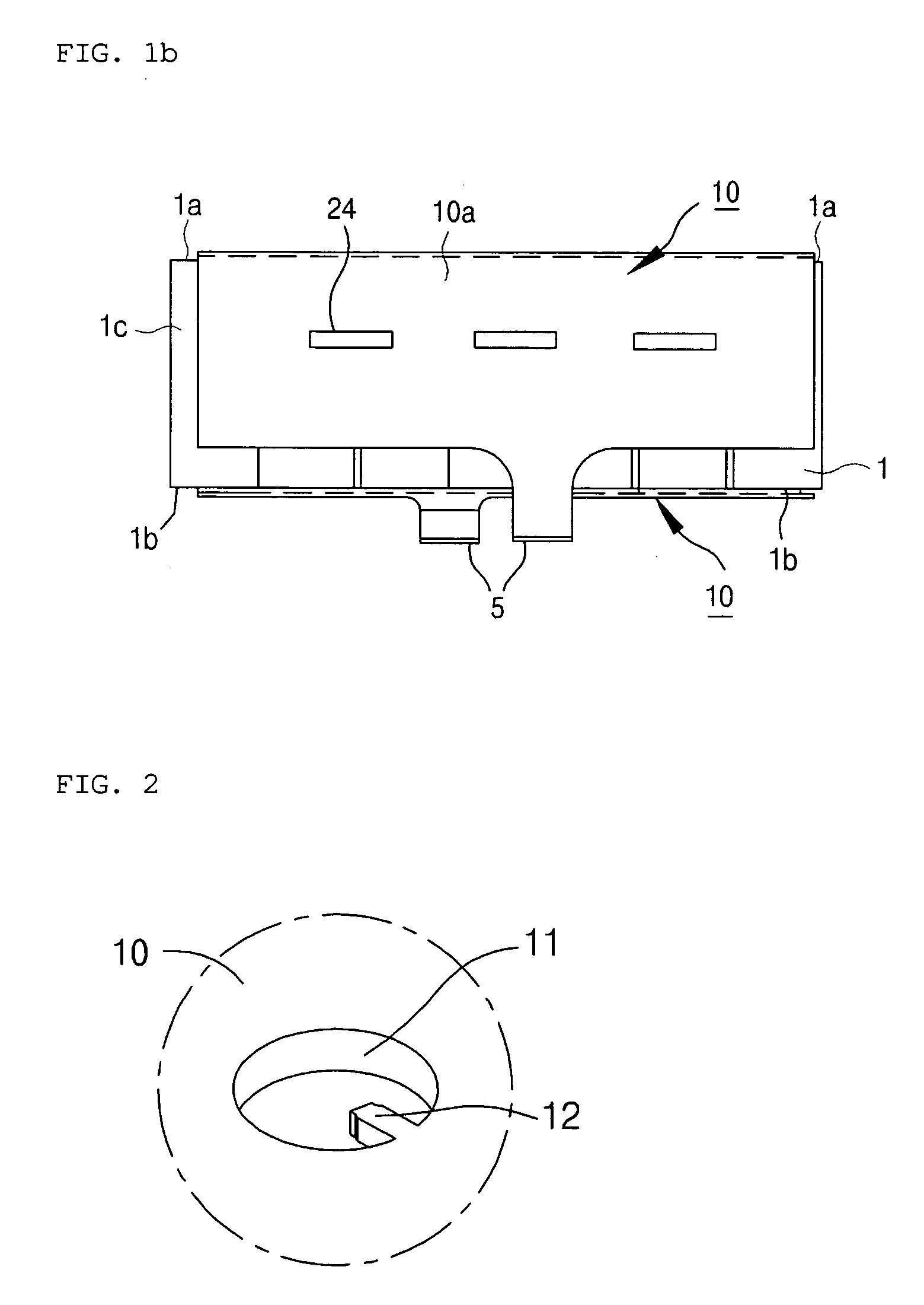
a bus-bar and capacitor technology, applied in the direction of fixed capacitors, laminated bus-bars, electrochemical generators, etc., can solve the problems of poor bonding, poor bonding, and small holes formed on the surface of the bus-bar b>10/b> that are too small to conveniently perform soldering, so as to achieve faster soldering operation, improve the quality of soldered parts, and reduce the whole weight of the bus-bar
- Summary
- Abstract
- Description
- Claims
- Application Information
AI Technical Summary
Benefits of technology
Problems solved by technology
Method used
Image

Examples
Embodiment Construction
Hereinafter, an exemplary embodiment of the present invention will be described in detail with reference to the accompanying drawings.
FIG. 3 is an exploded perspective view of a capacitor module adopting a bus-bar according to the embodiment of the present invention and FIG. 4 is a sectional view showing the capacitor device attached with the bus-bar being housed in an outer case. FIGS. 5A and 5B are enlarged perspective views of a portion B shown in FIG. 3 to show a lead frame according to first and second embodiments of the present invention, respectively. FIGS. 6A and 6B are plan views of the capacitor device attached with the bus-bars having different arrangements of opening parts, according to the embodiment of the present invention.
In a bus-bar 20 for assembling a capacitor device 1, opening parts 21 are cut at uniform intervals, more preferably, with respect to the middle of two adjoining capacitor devices 1 to expose polar plates 1a and 1b of the two adjoining capacitor devi...
PUM
 Abstract
Description
Claims
Application Information