Lead assembly and method of making same

a technology of lead and connector block, which is applied in the field of implantable leads, can solve the problems that the medical practitioner can have a difficult time inserting the connector end of the lead into the connector block of the ipg withou

Active Publication Date: 2011-09-13
BOSTON SCI NEUROMODULATION CORP
View PDF11 Cites 347 Cited by
  • Summary
  • Abstract
  • Description
  • Claims
  • Application Information

AI Technical Summary

Problems solved by technology

If the connector end is too soft or flexible, the medical practitioner can have a difficult time inserting the connector end of the lead into the connector block of the IPG without the lead buckling.

Method used


Image

  • Lead assembly and method of making same
  • Lead assembly and method of making same
  • Lead assembly and method of making same

Examples


first embodiment

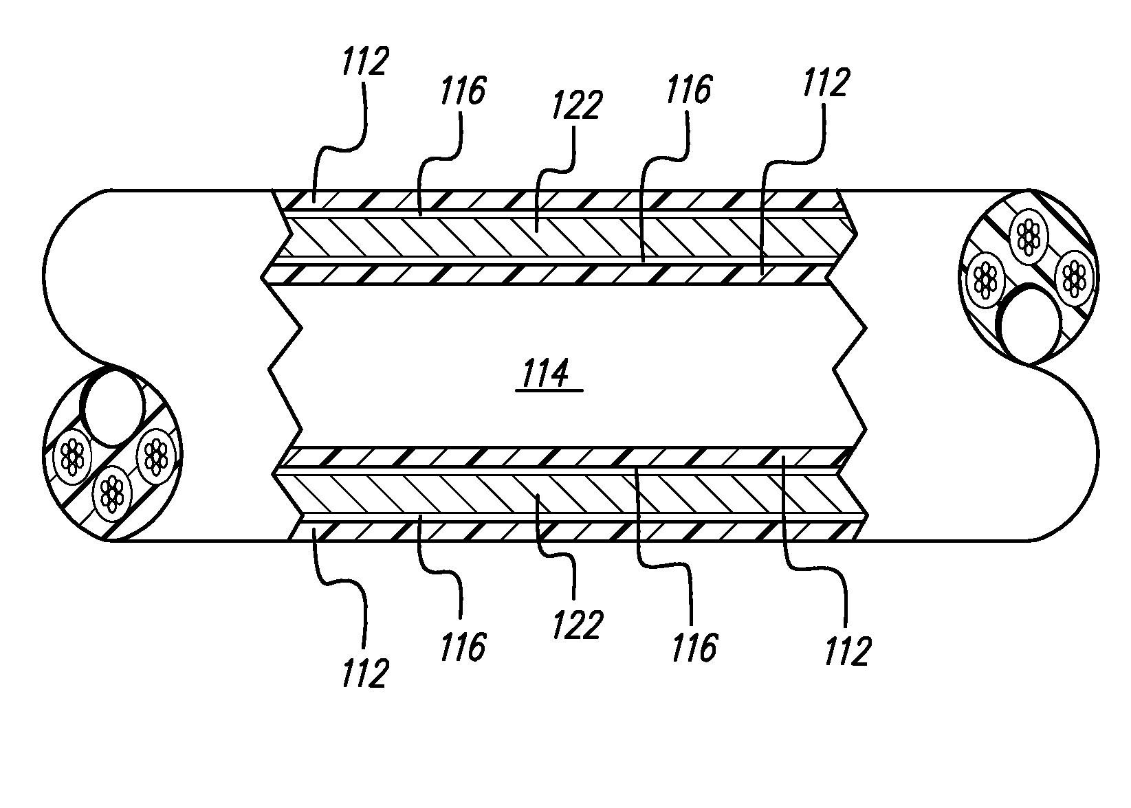
The lead has at least two terminal contacts at the proximal, connector end of the lead. There are two embodiments of materials that can be placed between the terminal contacts: (1) the first embodiment uses terminal spacers, with epoxy or another adhesive-like, electrically insulative material filling the voids or spaces within the terminal spacers and terminal contacts and between a terminal spacer and a terminal contact or (2) epoxy alone filling the separation gap between adjacent terminal contacts.

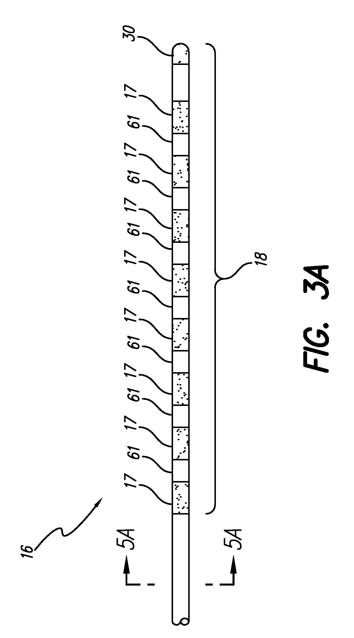
The distal end of the lead can be any type of electrode configuration that is known. For example, the distal end of the lead may be linear or percutaneous or it may be a paddle shape. The following show in more detail leads having proximal or connector ends as described in (1) and (2) above.

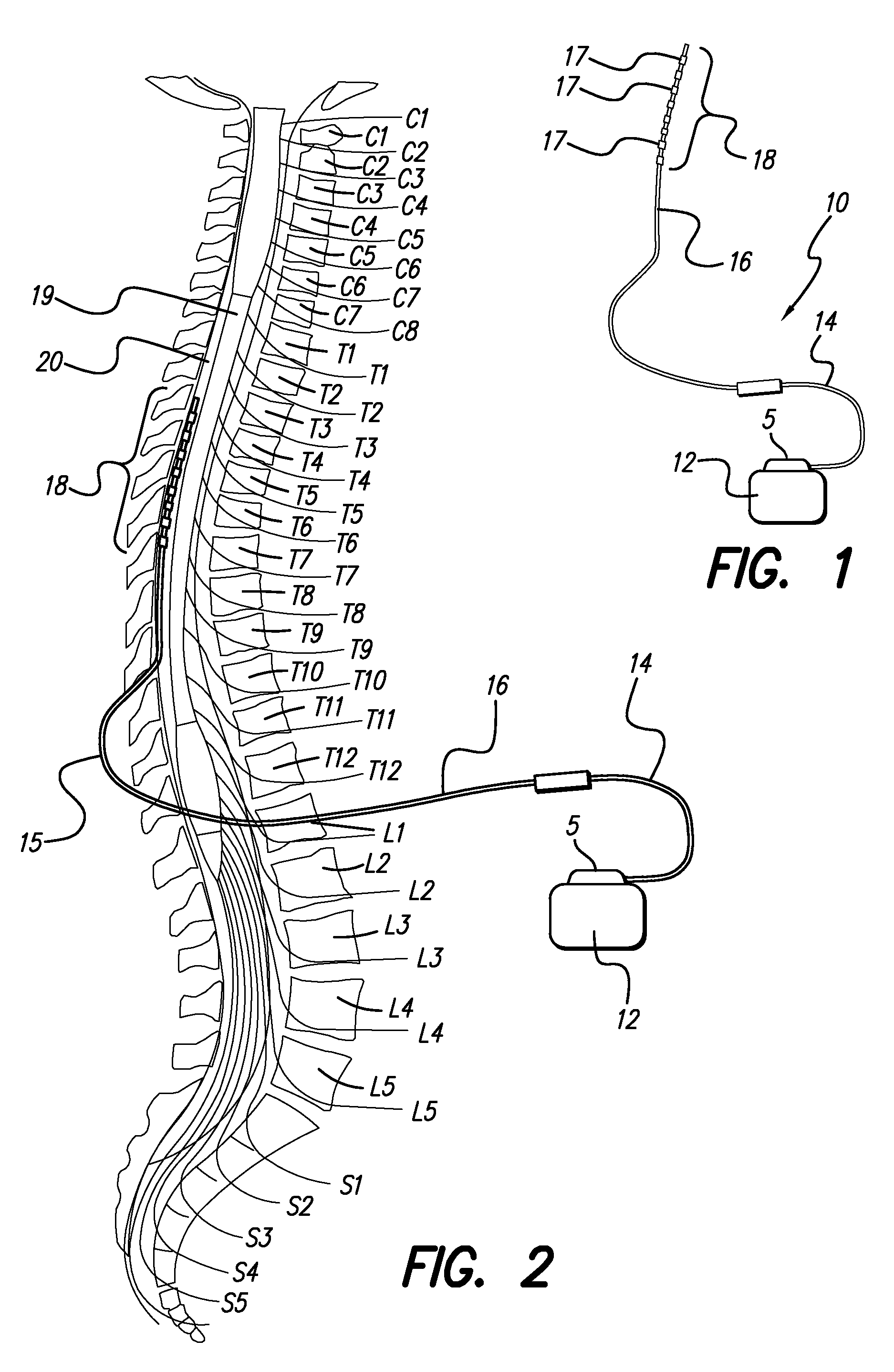
FIG. 3A shows a distal portion of a linear or percutaneous lead 16 that may include embodiments of the proximal lead construction as described above. The stimulating lead 16 is used to stimulate neu...

example 1

Any Lead with a Proximal End Having Terminal Spacers and Epoxy

The lead has a plurality of connector (terminal) contacts, e.g., eight terminal contacts at the proximal end of the lead. Between the terminal contacts are spacers. The terminal contacts are shaped as rings or configured to be ring-like. In particular, the terminal contacts may be cylindrical rings. The terminal spacers are also formed into rings or configured to be ring-like. In particular they may also be cylindrical rings. The terminal spacers may be made from a number of materials. For example, the terminal spacers may be made from polyurethane, e.g., Pellethane™ 55D polyurethane. Other suitable materials include polyetherether ketone or polyarylether ketone (collectively, PEEK), polysulfone, polyester, silicone, and polyethylene. The choice of terminal spacer materials may be determined based on desired stiffness at the proximal end of the lead. For example PEEK and Polysulfone material may be harder than a 55D polyu...

example 2

Linear Lead with Proximal, Terminal Spacers and Epoxy and Linear Distal End

The lead is linear and includes a proximal portion of the lead which is described in Example 1. Thus, the proximal end of the lead has a terminal spacer that is made from the group of materials: PEEK, polysulfone, polyester, silicone, and polyethylene. Epoxy may be applied, e.g., injected, in void spaces within the terminal spacers and terminal contacts and between a terminal spacer and an adjacent terminal contact. The distal end of the lead is linear and includes a plurality of electrode contacts, preferably formed into a ring or ring-like configuration, and more preferably a cylindrical ring. The distal end of the lead can optionally use electrode contact spacers, e.g., of polyurethane.


PUM


Abstract

A lead assembly and a method of making a lead are provided. The lead comprises a terminal, proximal end having a plurality of terminal contacts and material separating the terminal contacts. In one embodiment of the lead, the terminal contacts are separated by a preformed spacer, that may be made from various hard materials such as polyurethane, PEEK and polysulfone. Epoxy may be used to fill spaces at the proximal lead end, including between the spacer and terminal contacts. In one embodiment of the lead, the terminal contacts are separated by epoxy only. The lead may include a plurality of conductor lumens that contain conductors. The lead may also include a stylet lumen for accepting a stylet.

Description

FIELD OF THE INVENTIONThe present invention relates to implantable leads for providing electrical stimulation.BACKGROUNDMany types of implantable leads are currently used to treat a variety of maladies. In one example, a multiple electrode contact lead is used to treat chronic pain through stimulation of the spinal cord. “Electrode contact” will be used herein to refer to that conductive surface on the lead that delivers or sinks electrical current to or from tissue. Typical electrode contact material are platinum or platinum / iridium alloy.Spinal cord stimulation systems generally have two implantable components: an implantable pulse generator (IPG) and at least one stimulation lead connected to one output of the IPG. Generally, however, the IPG is a multi-channel device capable of delivering electrical current through the multiple electrode contacts of the lead.The term “lead” used herein will refer generally to any elongate device having any conductor or conductors, covered with a...

Claims


Application Information

Patent Timeline
Patent Type & Authority Patents(United States)
IPC IPC(8): A61N1/05
CPCA61N1/0551A61N1/0553
Inventor KUZMA, JANUSZ APIANCA, ANNE MWALTER, JERYLE LGIRGIS, MILAD
Owner BOSTON SCI NEUROMODULATION CORP
Why Eureka
Try Eureka