
System, methods and apparatus for generation of simulation stimulus

a technology of stimulus generation and simulation, applied in the field of integrated circuits, can solve the problems of increasing forcing the complexity of ic's to skyrocket, and increasing the complexity of design, verification, and manufacture of ics, and may be one of the more difficult parts of the design process

Inactive Publication Date: 2011-09-13
CADENCE DESIGN SYST INC
View PDF16 Cites 9 Cited by
  • Summary
  • Abstract
  • Description
  • Claims
  • Application Information

AI Technical Summary

Benefits of technology

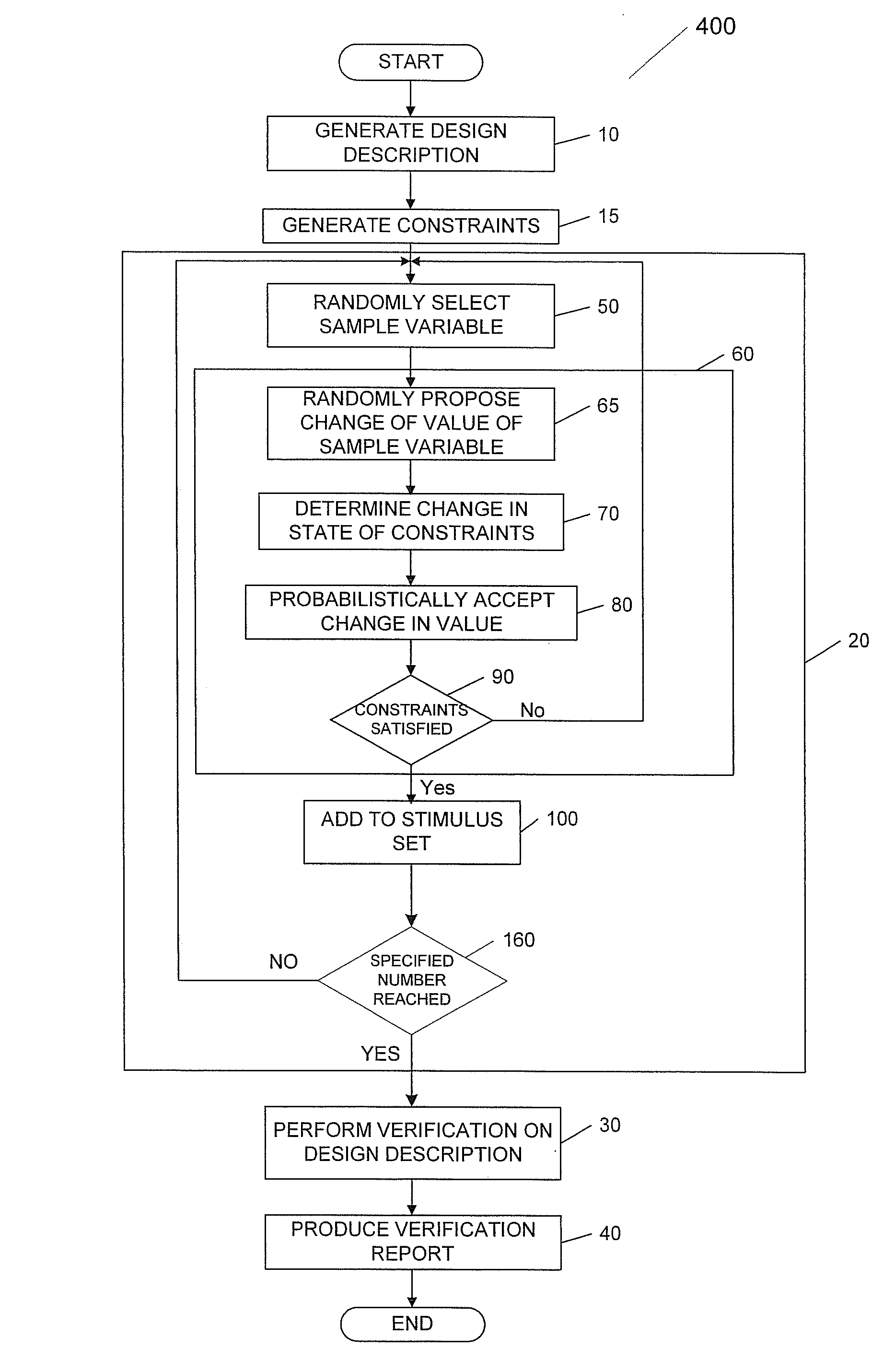
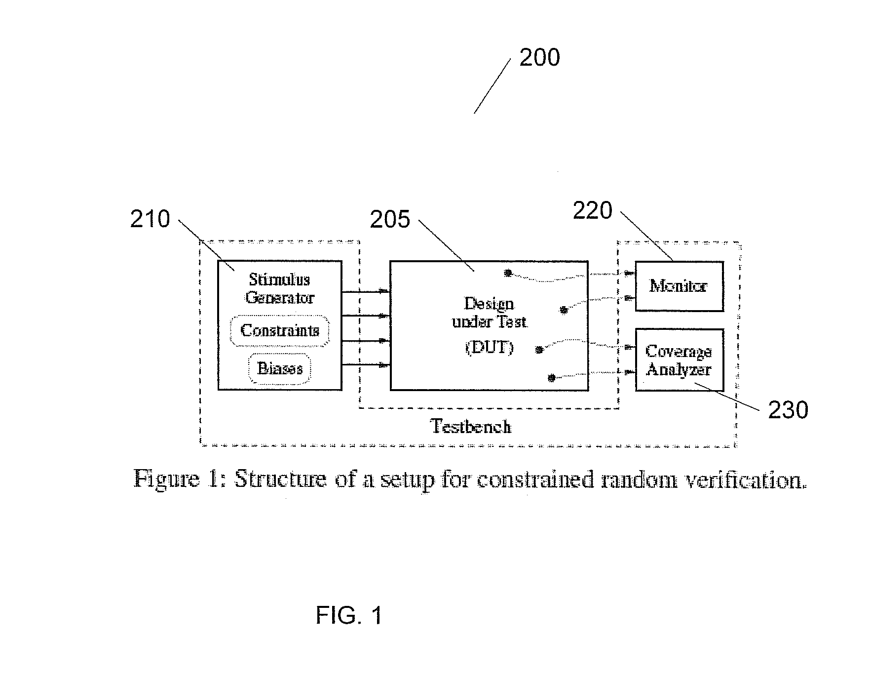
[0007]Various embodiments of the present invention allow for fast generation of integrated circuit design verification, mixed with Boolean / integer input stimuli, that have a well-defined (uniform) distribution. In one embodiment, the stimulus generator is runtime- and memory-efficient for a large set of practical constraints. Various embodiments of the stimulus generator can be implemented in hardware, thus supporting the use of hardware emulation / acceleration to accelerate the testbench for specific constraint sets. Various embodiments of the present invention were published and a reduction to practice discussed in Kitchen, N.; Kuehlmann, A., “Stimulus generation for constrained random simulation,” Proceedings of the 2007 IEEE / ACM International Conference on Computer Aided Design pp 258-265, November 2007 which is hereby incorporated by reference in its entirety. This paper was presented at ICCAD 2007, San Jose Calif. 4-8 Nov. 2007.

Problems solved by technology

The increased demand for functionality of consumer electronics has forced the complexity of IC's to skyrocket.
These demands create increased complexity on the design, verification, and manufacture of ICs.
Creation and verification RTL design may be one of the more difficult portions of the design process.
In many instances, this verification is a very difficult and time intensive task.
The efficiencies of these approaches typically fail in either their ability to provide good uniform distribution of stimulus over the solution set, or in their run-time and memory efficiency.
Further, some approached perform well for small problems but their performance degrades substantially with the size of the problem.

Method used


Image

  • System, methods and apparatus for generation of simulation stimulus
  • System, methods and apparatus for generation of simulation stimulus
  • System, methods and apparatus for generation of simulation stimulus

Examples


Embodiment Construction

[0025]In the following paragraphs, the present invention will be described in detail by way of example with reference to the attached drawings. While this invention is capable of embodiment in many different forms, there is shown in the drawings and will herein be described in detail specific embodiments, with the understanding that the present disclosure is to be considered as an example of the principles of the invention and not intended to limit the invention to the specific embodiments shown and described. That is, throughout this description, the embodiments and examples shown should be considered as exemplars, rather than as limitations on the present invention. Descriptions of well known components, methods and / or processing techniques are omitted so as to not unnecessarily obscure the invention. As used herein, the “present invention” refers to any of the embodiments of the invention described herein, and any equivalents. Furthermore, reference to various feature(s) of the “...


PUM


Abstract

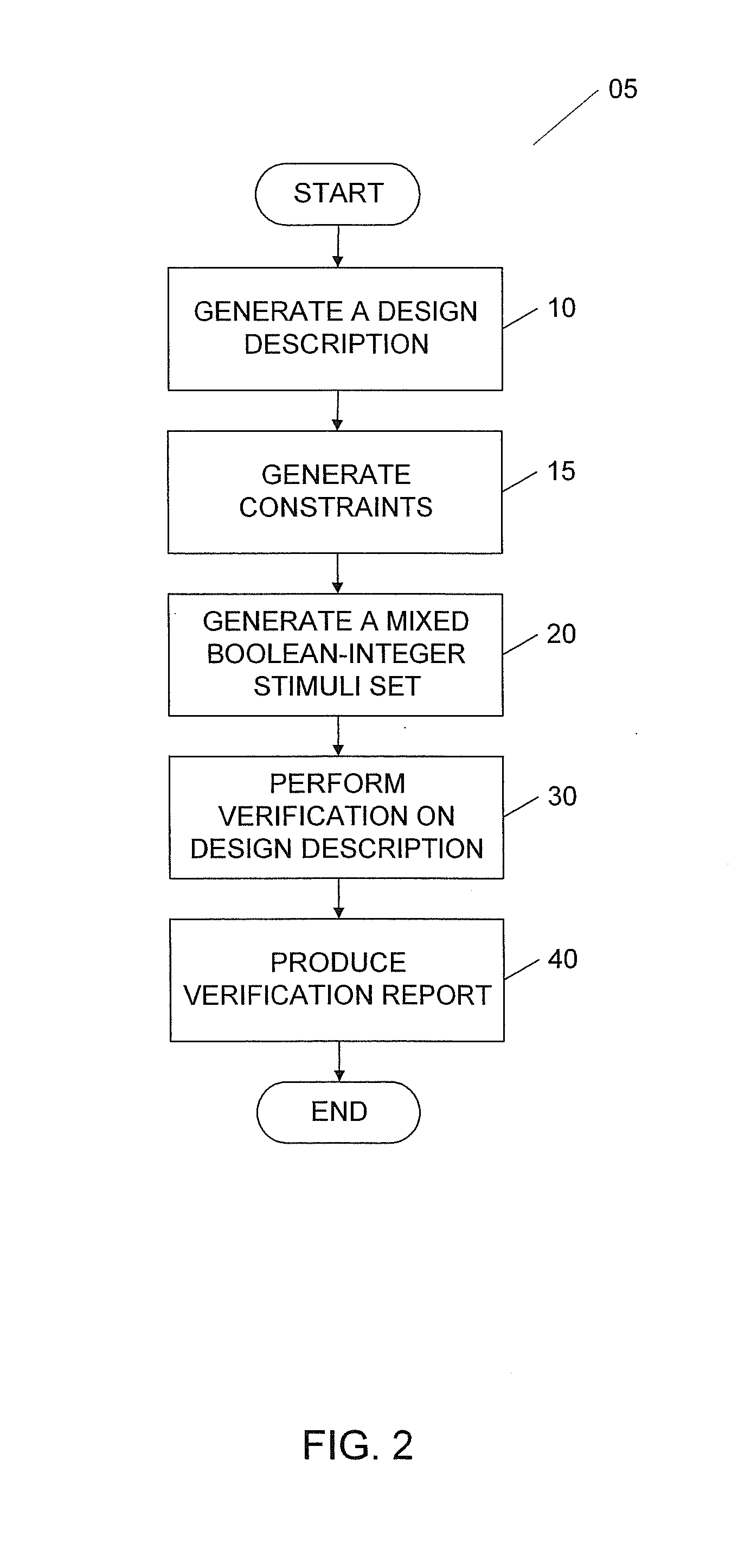
A method and apparatus for producing a verification of digital circuits is provided. In an exemplary embodiment, a set of Boolean and Integer constraints are derived, and a set of Boolean and Integer stimuli are generated that meet the constraints. These stimuli are then used to verify a digital design, and a verification report is generated. In other example embodiments, a computing apparatus and computer software product are provided. The computer software product containing a set of executable instructions that, when executed, configure the computing apparatus to produce a verification report by the provided methods.

Description

FIELD OF THE INVENTION[0001]The present invention generally relates to integrated circuits. More particularly, the invention concerns methods and apparatus for generation of stimulus for verification of integrated circuit designs.BACKGROUND OF THE INVENTION[0002]Integrated circuits (ICs) have become the backbone of modern consumer electronics. The increased demand for functionality of consumer electronics has forced the complexity of IC's to skyrocket. In a number of applications, ICs must be highly functional, low cost and have low power consumption. These demands create increased complexity on the design, verification, and manufacture of ICs.[0003]A typical IC design may involve the creation of electronic components, such as transistors and resistors, and the interconnections of these components onto a substrate, such as silicon. Functional verification of a digital design involves the verification that the design conforms to the specification. Functional verification may involve ...

Claims


Application Information

Patent Timeline
Patent Type & Authority Patents(United States)
IPC IPC(8): G06F17/50
CPCG06F17/504G06F30/3323
Inventor KUEHLMANN, ANDREASKITCHEN, NATHAN
Owner CADENCE DESIGN SYST INC
Learn More