Braking system for high speed and power rotating machinery

a technology of rotating machinery and braking system, which is applied in the direction of braking system, fluid actuated brake, transportation and packaging, etc., can solve the problems of large heat, damage or destruction of rotor and other energy storage device components, design and development efforts, etc., and achieve the effect of large braking force area, and inefficient hydraulic fluid characteristics

Active Publication Date: 2011-09-20
THE BOEING CO
View PDF20 Cites 2 Cited by
  • Summary
  • Abstract
  • Description
  • Claims
  • Application Information

AI Technical Summary

Benefits of technology

[0005]The brake mechanism of the present invention includes a pair of annular brake pads disposed adjacent opposed surfaces of a flywheel rotor. The brake friction surfaces, which are kept apart by springs during normal flywheel operation, contact the full annular surface area of both sides of the rotor when the brake is applied. By applying pressure to the lower half of the brake caliper, a lifting force is provided which, when precisely controlled, allows the static flywheel rotor to be suspended at the desired height for chilling the superconducting bearing cryostat and setting the magnetic suspension height of the flywheel rotor before commencing rotor spinning. The brake mechanism also laterally restricts movement of the flywheel rotor when not in motion for precise positioning of the rotor within the brake mechanism. During brake applications, cooling water or hydraulic fluid is forced under pressure through the caliper's passages, providing a clamping force and removing the heat generated by the engagement of the friction materials. The present invention is capable of operating with water which has inefficient hydraulic fluid characteristics because the inventive brake mechanism provides a large braking force area of application and is capable of accommodating the lower pressure requirements of water. In the event the rotor drifts out of its permitted vertical envelope, an external system not part of the present invention applies braking on the spinning rotor. In the event vibration causes the rotor to leave its predetermined safe lateral envelope of operation, the annular brake pads apply a radially inward force on the rotor for maintaining the required rotor lateral positioning. The brake calipers may be replaced as a “cartridge” and can be replaced as necessary without affecting any other part or component of the flywheel system. The frictional components of the brake mechanism can be easily replaced as an assembly such as where system requirements dictate that the friction components be a one time use item such as when used in an emergency.

Problems solved by technology

These types of flywheel rotors typically have a composite composition and are the product of extensive design and development efforts and are expensive.
Stopping a rotor such as for an emergency requires the application of a large torque on the rotor resulting in the generation of large amounts of heat which can damage or destroy the rotor and other energy storage device components.
An emergency may arise because of a loss of cryostat cooling, a loss of vacuum within which the flywheel rotor operates, or the loss of the energy storage device's computer control system.
To date, the inability to safely stop a high speed, high energy magnetically suspended flywheel rotor in an energy storage device and to consistently and precisely position the rotor within the energy storage device have limited the use of these types of devices in commercial environments and applications.

Method used


Image

  • Braking system for high speed and power rotating machinery
  • Braking system for high speed and power rotating machinery
  • Braking system for high speed and power rotating machinery

Examples


Embodiment Construction

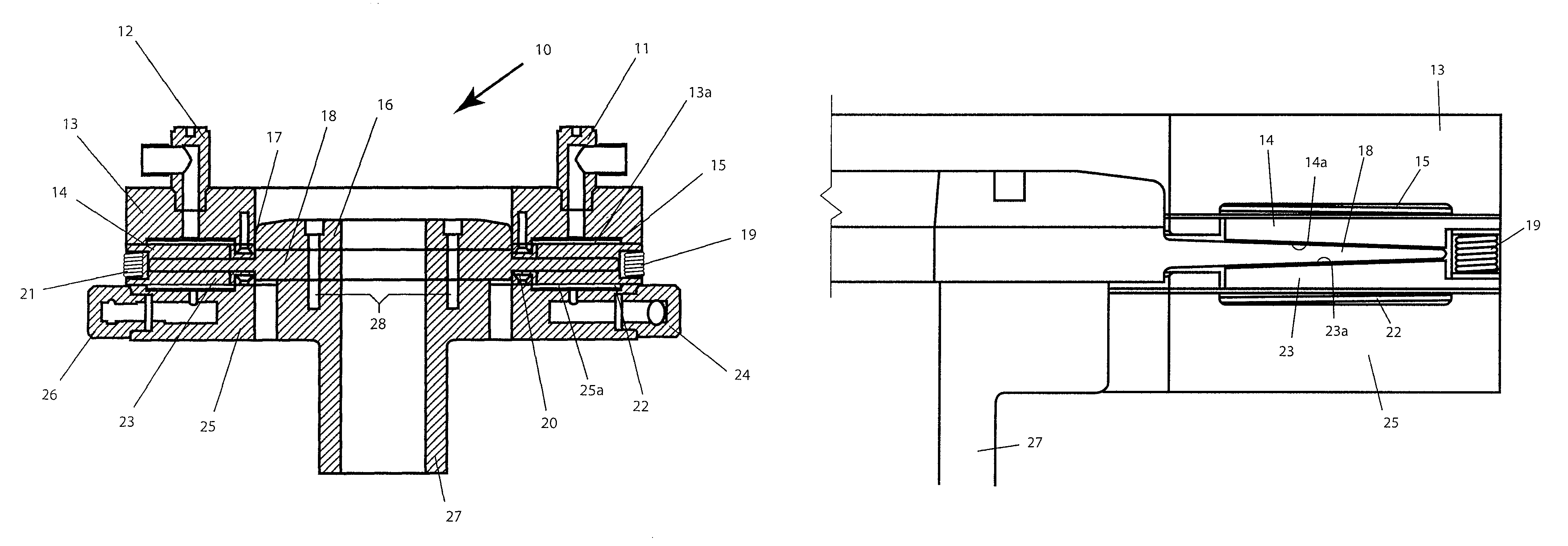
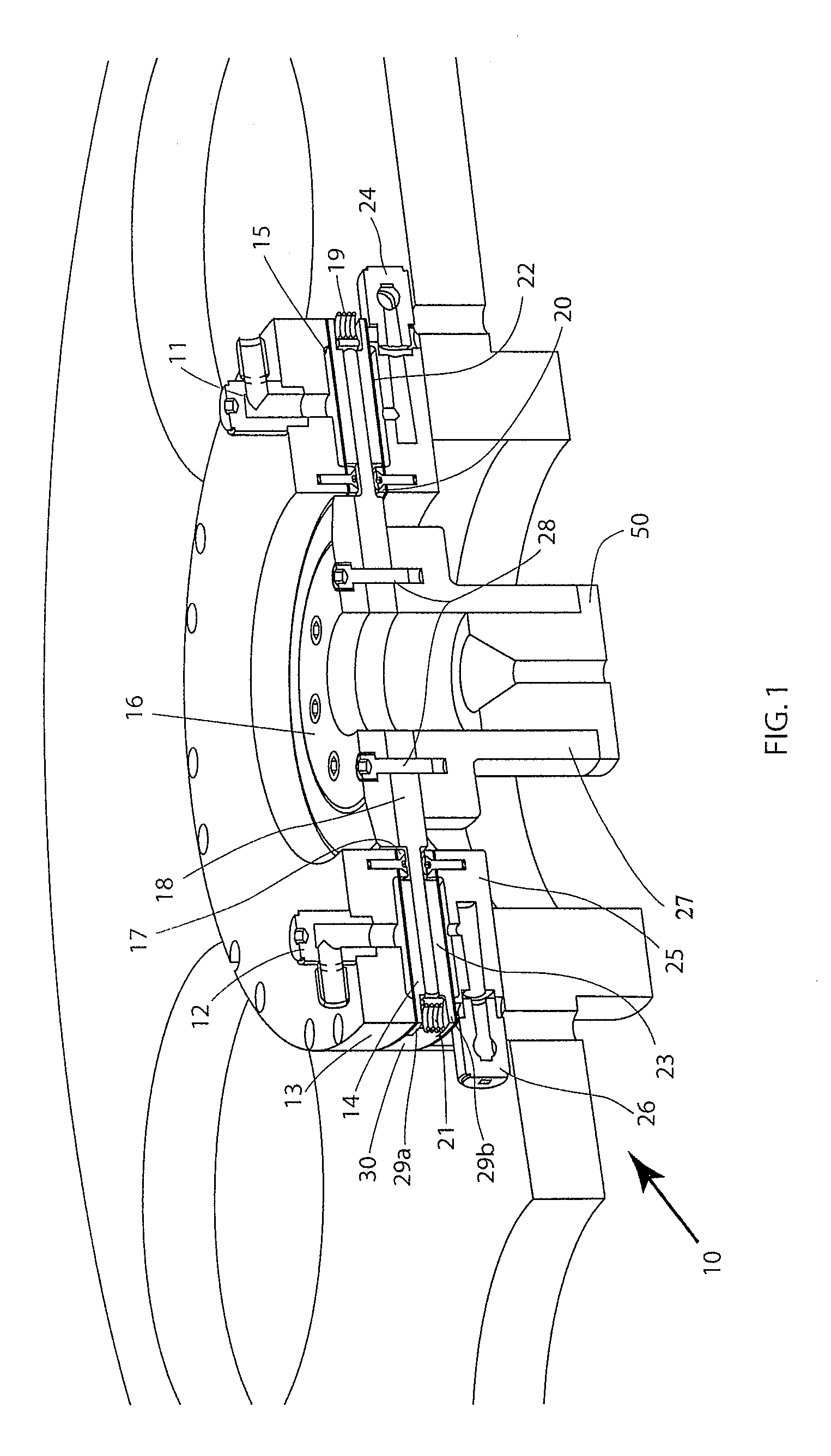
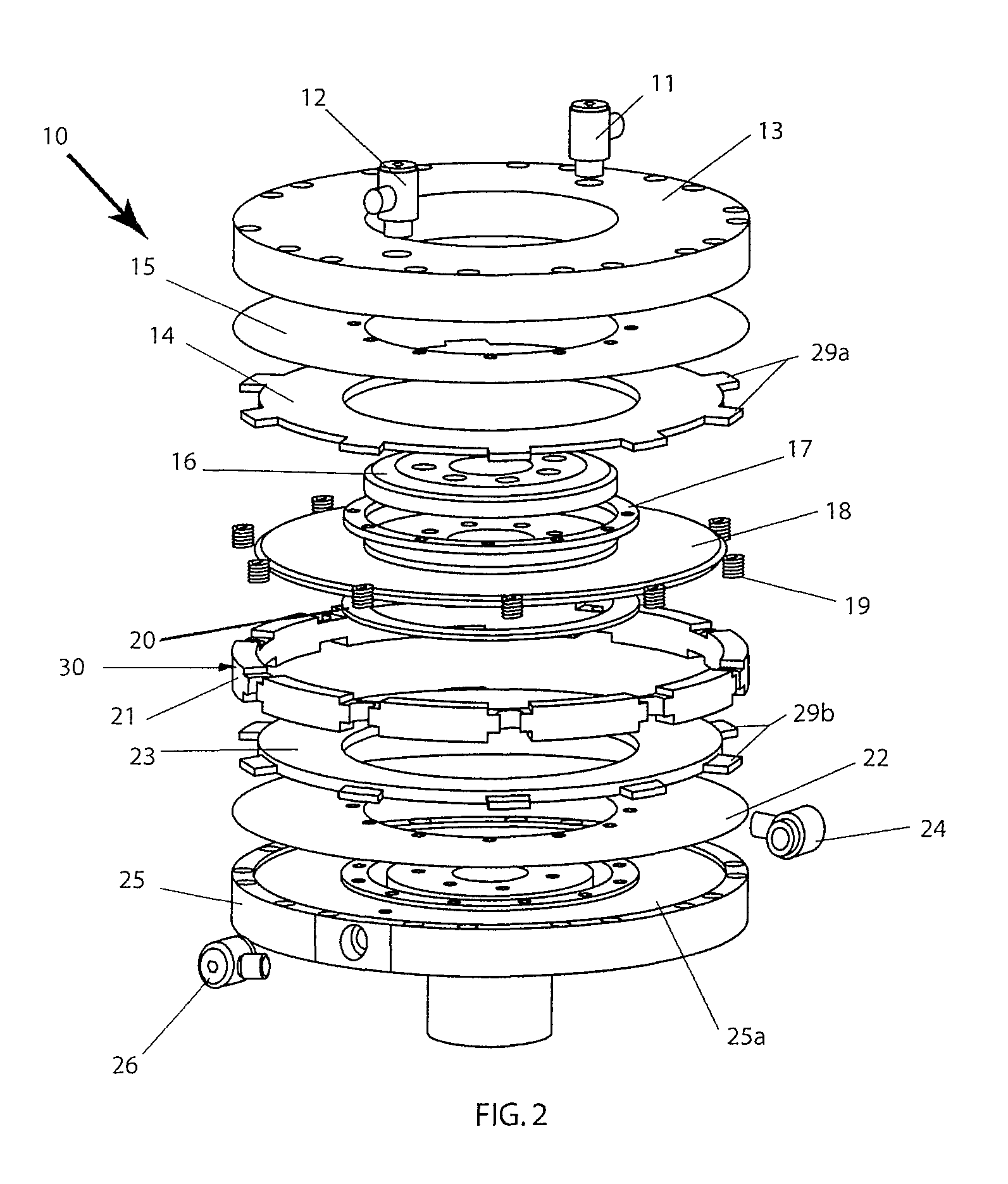
[0012]Referring to FIG. 1, there is shown a perspective, partially cutaway view of a brake system 10 in accordance with the principles of the present invention. FIGS. 2 and 3 are respectively exploded perspective and vertical sectional views of the brake system 10. FIGS. 4 and 5 are partial, enlarged sectional views of portions of the brake system 10 shown in FIG. 3.

[0013]The brake system 10 of the present invention includes a brake disc rotor 18 attached to a main shaft 27 as well as to a rotating body 50 by means of a retainer plate 16 and plural threaded bolts 28 concentrically disposed in a spaced manner about aligned center apertures in each of the retainer plate, brake disc rotor and main shaft. The brake disc rotor 18 is preferably comprised of a high strength, annular heat resistant composite material, such as carbon-carbon, and is disposed between first and second annular brake disc pads 14 and 23. Each of the first and second brake disc pads 14 and 23 includes respective p...


PUM


Abstract

A braking system for a high speed, high load rotor operating in a vacuum and suspended by a magnetic field such as in a flywheel energy storage device includes a pair of calipers disposed on opposed sides of the rotor for actuating a pair of annular friction discs into engagement with opposed sides of the rotor. Each caliper includes a mounting ring on its outer edge and an inner shallow annular groove in which it disposed one of the friction discs. A circulating fluid under pressure is directed into each annular groove for urging each friction disc into engagement with one of the opposed surfaces of the rotor for safely bringing the rotor to a stop such as in an emergency. The circulating fluid removes the heat generated by the braking action, while the controlled pressure applied by the discs also controls the position of the rotor when static such as during initialization.

Description

FIELD OF THE INVENTION[0001]This invention relates generally to a braking system for a high speed, high load rotating system, such as a flywheel energy storage device, which also dissipates energy generated during braking.BACKGROUND OF THE INVENTION[0002]Disc brakes are commonly used in various applications such as in vehicles for slowing or stopping the vehicle. Disc brakes are also connected to the output shaft of a prime mover, such an internal combustion engine, for measuring the output power as in a dynamometer. Disc brakes are also increasingly being used in high energy storage devices employing a rotating flywheel for controlling the speed of rotation of the flywheel. In these types of applications, the disc brake engages a moving rotor for controlling the speed, or even stopping, the rotor.[0003]In a high speed flywheel energy storage device, the flywheel rotor is often magnetically suspended and operates at very high speeds. These types of flywheel rotors typically have a c...

Claims


Application Information

Patent Timeline
Patent Type & Authority Patents(United States)
IPC IPC(8): F16D55/02
CPCB60T1/10F16D2065/024F16D2065/782F16D2065/784F16D2121/02
Inventor MCIVER, CARL R.MCCRARY, KEVIN E.HULL, JOHN R.MITTLEIDER, JOHN A
Owner THE BOEING CO
Why Eureka
Try Eureka