
Rapid diagnostic device, assay and multifunctional buffer

a diagnostic device and multi-functional technology, applied in the direction of component separation, material testing goods, chemical methods analysis, etc., can solve the problems of color signal indicating negative, undue delay in the passage of fluid test samples through the membrane, etc., to increase the possibility of user error, facilitate flow through an exposed area, and effectively channel

Inactive Publication Date: 2011-09-27
MEDMIRA
View PDF29 Cites 21 Cited by
  • Summary
  • Abstract
  • Description
  • Claims
  • Application Information

AI Technical Summary

Benefits of technology

The solution enables rapid, reliable, and sensitive detection of target analytes with minimal equipment and training, maintaining assay sensitivity and specificity while reducing the number of steps and storage requirements, making it suitable for resource-limited settings.

Problems solved by technology

If the fluid test sample happens to contain the target analyte, the absence of a color signal will indicate a positive result due to the inability of the indicator reagent to bind to the capture reagent.
Alternatively, if the test sample does not contain any target analyte, the presence of a color signal will indicate a negative result due to the ability of the indicator reagent to bind to unoccupied sites of attachment of the capture reagent.
Moreover, it is believed that prior art devices which have relatively thin reaction membranes, such as nitrocellulose membranes less than 0.1 mm thick and which are not paper-backed, tend to allow the sample to flow sideways across the reaction membrane rather than downwards through the middle of the reaction membrane.
However, if the membrane thickness is to large, it may cause undue delay of the passage of the fluid test sample through the membrane.
Also, the use of a good quality paper-backed nitrocellulose may make a blocking step unnecessary in some assays.

Method used


Image

  • Rapid diagnostic device, assay and multifunctional buffer
  • Rapid diagnostic device, assay and multifunctional buffer
  • Rapid diagnostic device, assay and multifunctional buffer

Examples


Embodiment Construction

[0054]Unless defined otherwise, all technical and scientific terms used herein have the same meaning as commonly understood by one of ordinary skill in the art to which this invention belongs. It must also be noted that, as used in the specification and the appended claims, the singular forms “a,”“an” and “the” include plural referents unless the context clearly dictates otherwise. For example, reference to an “antigen” or “antibody” is intended to include a plurality of antigen molecules or antibodies.

[0055]Ranges may be expressed herein as from “about” or “approximately” one particular value and / or to “about” or “approximately” another particular value. When such a range is expressed, another embodiment includes from the one particular value and / or to the other particular value. Similarly, when values are expressed as approximations, by use of the antecedent “about,” it will be understood that the particular value forms another embodiment.

[0056]As employed throughout the disclosur...


PUM


Abstract

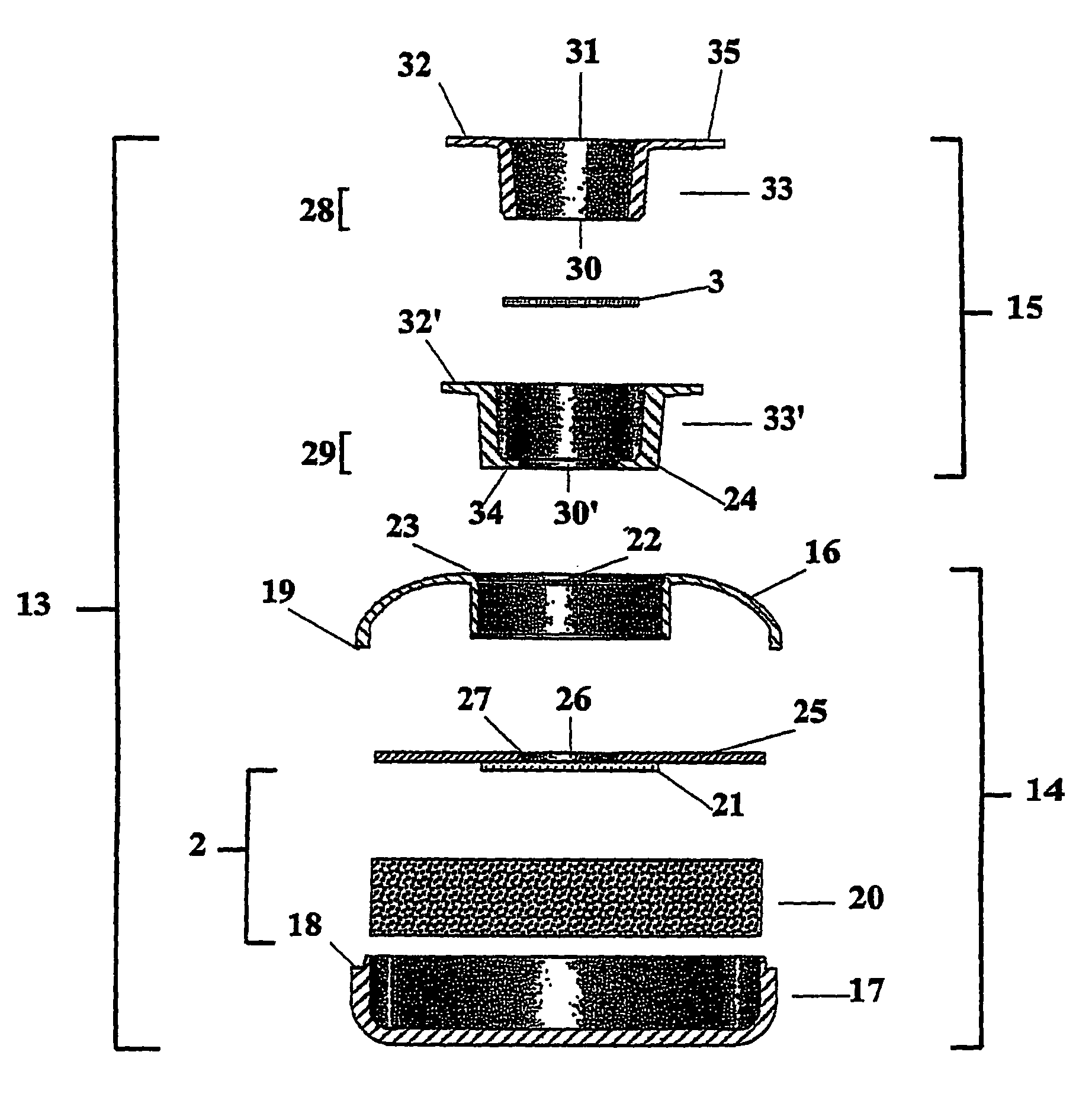
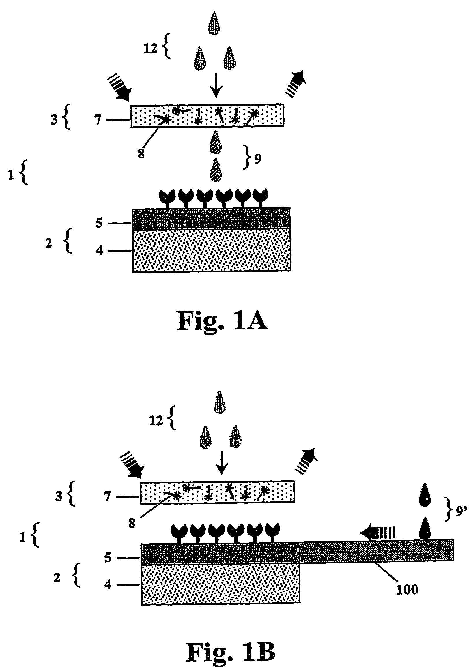
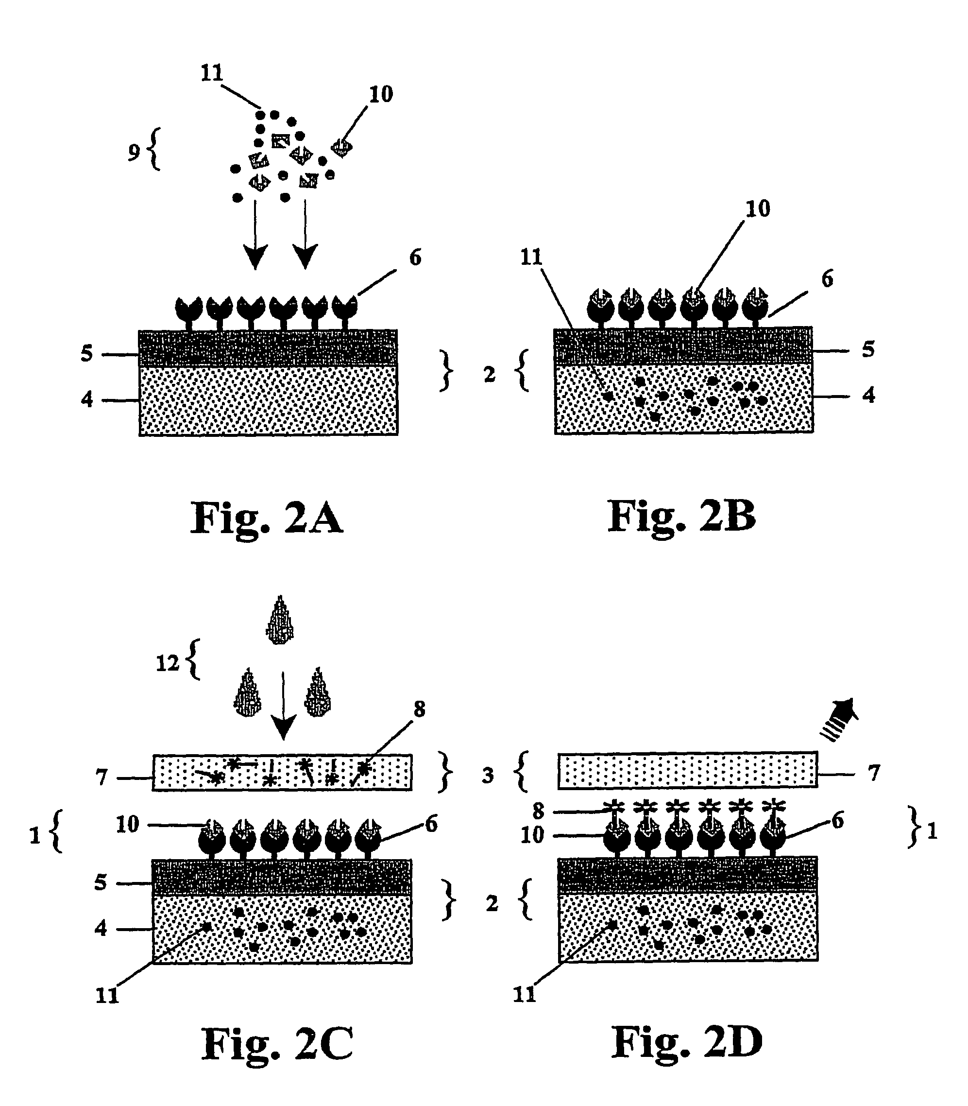
An improved rapid diagnostic device, assay and multifunctional buffer reagent are provided for the detection of a target analyte in a fluid test sample. The 2-step assay utilizes a dual component flow-through device comprising a test unit and a dried indicator reagent delivery unit capable of receiving the fluid sample and multifunctional buffer, respectively. The test unit comprises a reaction zone containing immobilized capture reagent that can specifically bind to the target analyte, an absorbent zone supporting the reaction zone, and optionally, a blood separation zone in lateral fluid communication with the reaction zone. The dried indicator reagent delivery unit comprises a label zone permeated with a dried indicator reagent which is capable of being placed in transient fluid communication with the reaction zone of the test unit during the assay procedure. The rapid diagnostic assay system reduces the number of assay reagents, method steps and time required for performance compared to other conventional assays.

Description

CROSS-REFERENCE TO RELATED APPLICATIONS[0001]This application is a continuation of application Ser. No. 10 / 163,675, filed Jun. 6, 2002,now U.S. Pat. No. 7,531,362, which claims the benefit of Provisional Application Nos. 60 / 296,147 and 60 / 309,477, filed Jun. 7, 2001 and Aug. 3, 2001, respectively, the entire contents of which are hereby incorporated by reference in this application.FIELD OF THE INVENTION[0002]An improved rapid diagnostic device, assay and multifunctional buffer are provided for the detection of a target analyte in a fluid test sample. The assay utilizes a multifunctional buffer reagent and flow-through device comprising a test unit in combination with a detachable dried indicator reagent delivery unit. A method for utilizing the flow-through device, a test kit and a formulation for generating the multifunctional buffer are also provided.BACKGROUND OF THE INVENTION[0003]Diagnostic assays have become an indispensable aid in medical and research fields for detecting a ...

Claims


Application Information

Patent Timeline
Patent Type & Authority Patents(United States)
IPC IPC(8): G01N33/48G01N33/543
CPCG01N33/5302G01N33/54366G01N33/54386Y10T436/10Y10T436/108331G01N33/54388G01N33/54391
Inventor CHAN, HERMES K. W.
Owner MEDMIRA
Learn More