Measuring apparatus and method, processing apparatus and method, pattern forming apparatus and method, exposure apparatus and method, and device manufacturing method

a technology of exposure apparatus and manufacturing method, which is applied in the direction of photomechanical apparatus, printing, instruments, etc., can solve the problems of difficult positioning of the multi-point af system described above in the vicinity of the projection optical system, the surface of the wafer as a substrate to be exposed is not always flat, and the focus margin at the time of exposure operation becomes insufficient, etc., to achieve high accuracy and high-precision pattern formation

Inactive Publication Date: 2011-09-27
NIKON CORP
View PDF165 Cites 8 Cited by
  • Summary
  • Abstract
  • Description
  • Claims
  • Application Information

AI Technical Summary

Benefits of technology

With this apparatus, the encoder system whose measurement values have favorable short-term stability measures position information of the movable body within the plane with high precision without being affected by air fluctuations, and also the surface position measuring system measures position information of the movable body in a direction orthogonal to the plane with high precision without being affected by air fluctuations. In this case, since both the encoder system and the surface position measuring system directly measure the surface of the movable body, simple and direct position control of the movable body can be performed.
With this method, position information of the surface of the movable body in a third direction orthogonal to the plane is measured with high accuracy by the measuring unit, being hardly affected by air fluctuations.

Problems solved by technology

However, the surface of a wafer as a substrate to be exposed is not always flat due to, for example, undulation of the wafer or the like.
On the other hand, there has been a possibility that the focus margin at the time of exposure operation becomes insufficient because a depth of focus becomes so narrow due to the shorter wavelength of exposure light and the larger NA of the projection optical system.
However, in exposure apparatuses that makes use of the liquid immersion method, or other exposure apparatuses in which a distance (working distance) between the lower end surface of the projection optical system and the wafer is short, it is difficult to place the multipoint AF system described above in the vicinity of the projection optical system.
However, an optical path of a beam of the laser interferometer that measures the position of the stage is as long as several hundred mm or more, and in addition, position control of the stage with higher accuracy has been required due to finer patterns to cope with semiconductor devices with higher integration, and therefore, short-term fluctuation of measurement values of the laser interferometer which is caused by temperature fluctuations (air fluctuations) of the atmosphere on the beam path of the laser interferometer is becoming unignorable now.

Method used


Image

  • Measuring apparatus and method, processing apparatus and method, pattern forming apparatus and method, exposure apparatus and method, and device manufacturing method
  • Measuring apparatus and method, processing apparatus and method, pattern forming apparatus and method, exposure apparatus and method, and device manufacturing method
  • Measuring apparatus and method, processing apparatus and method, pattern forming apparatus and method, exposure apparatus and method, and device manufacturing method

Examples


Embodiment Construction

An embodiment of the present invention will be described below, with reference to FIGS. 1 to 36.

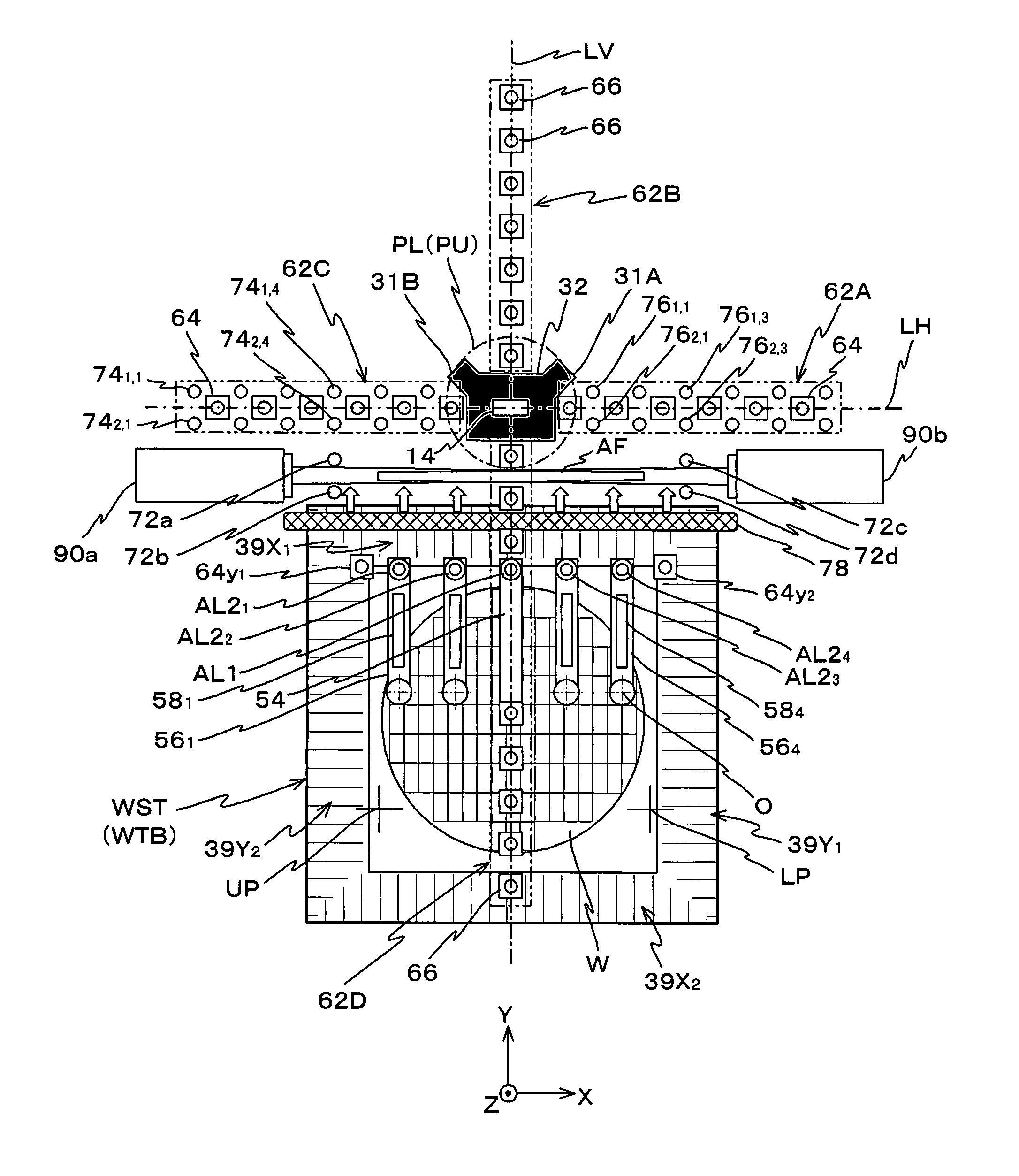
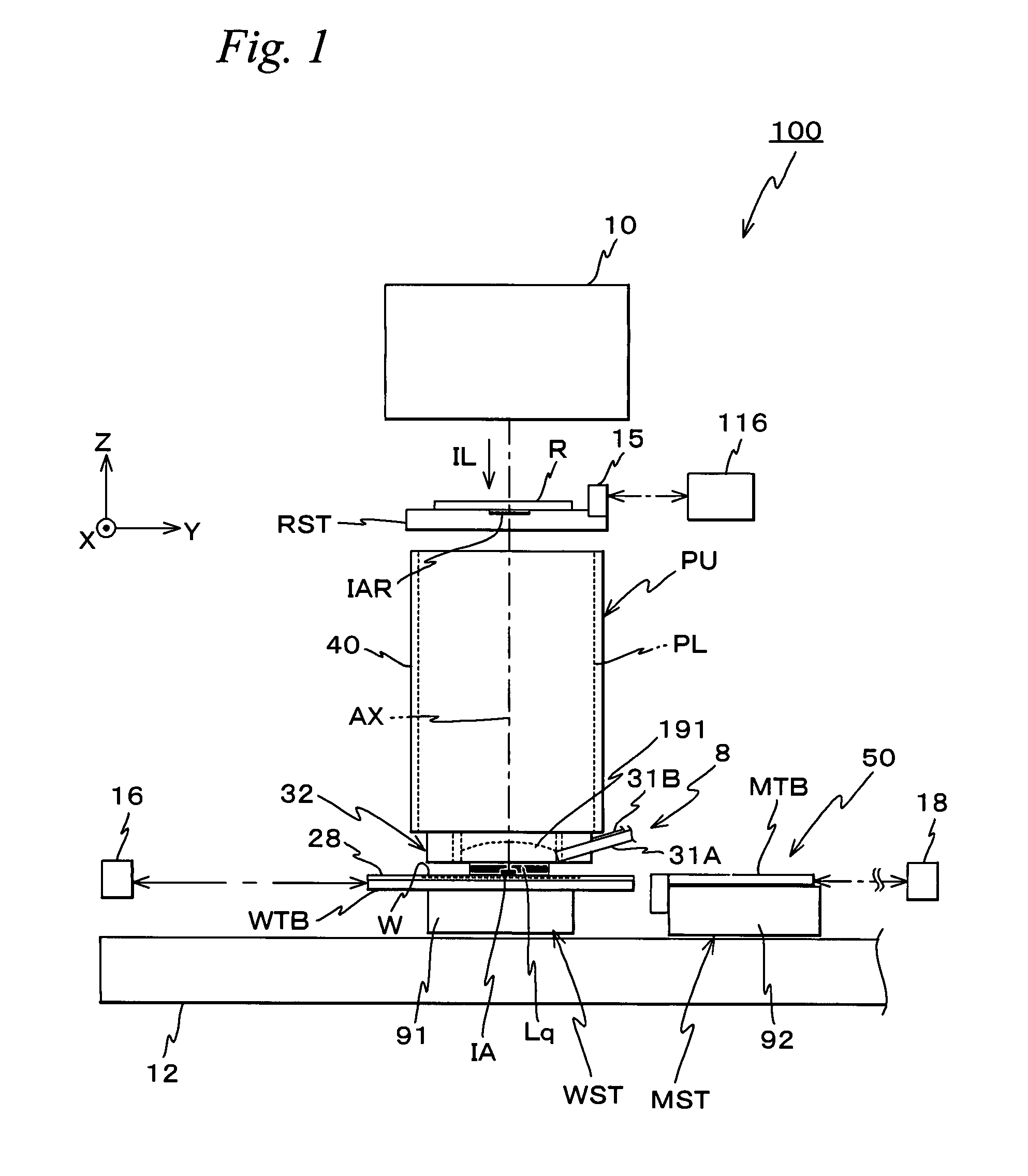
FIG. 1 schematically shows the configuration of an exposure apparatus 100 related to an embodiment. Exposure apparatus 100 is a scanning exposure apparatus by a step-and-scan method, that is, a so-called scanner. As will be described later, in the embodiment, a projection optical system PL is arranged, and the following description will be made assuming that a direction parallel to an optical axis AX of projection optical system PL is a Z-axis direction, a direction in which a reticle and a wafer are relatively scanned within a plane orthogonal to the Z-axis direction is a Y-axis direction and a direction that is orthogonal to a Z-axis and a Y-axis is an X-axis direction, and rotation (tilt) directions around the X-axis, the Y-axis and the Z-axis are θx, θy and θz directions respectively.

Exposure apparatus 100 is equipped with an illumination system 10, a reticle stage RST that holds a re...


PUM


Abstract

Position information of a movable body within an XY plane is measured with high accuracy by an encoder system whose measurement values have favorable short-term stability, without being affected by air fluctuations, and also position information of the movable body in a Z-axis direction orthogonal to the XY plane is measured with high accuracy by a surface position measuring system, without being affected by air fluctuations. In this case, since both of the encoder system and the surface position measuring system directly measure the upper surface of the movable body, simple and direct position control of the movable body can be performed.

Description

BACKGROUND OF THE INVENTION1. Field of the InventionThe present invention relates to measuring apparatuses and methods, processing apparatuses and methods, pattern forming apparatuses and methods, exposure apparatuses and methods, and device manufacturing methods, and more particularly to a measuring apparatus and a measuring method that measure position information of a movable body that moves within a plane, a processing apparatus and a processing method that perform a predetermined processing to an object mounted on a movable body that moves within a plane, a pattern forming apparatus that is equipped with the measuring apparatus or the processing apparatus and a pattern forming method that includes the measuring methods, an exposure apparatus and an exposure method that expose an object with an energy beam via an optical system, and a device manufacturing method in which either one of the measuring method, the processing method, the exposure apparatus or the exposure method is u...

Claims


Application Information

Patent Timeline
Patent Type & Authority Patents(United States)
IPC IPC(8): G03B27/42G03B27/58G01B11/14
CPCG03F7/70775G01D5/38G03F7/70341G03F7/70666G03F9/7026G01D2205/90G01D2205/95G03F7/70216G03F7/70483G03F7/70491G03F7/70191
Inventor SHIBAZAKI, YUICHI
Owner NIKON CORP
Why Eureka
Try Eureka