Manufacture and use of parallel eccentric electro-mechanical actuator

a technology of electro-mechanical actuators and eccentrics, which is applied in the direction of oblique crank gearings, gearings, hoisting equipments, etc., can solve the problems of complex design of mechanical systems using actuators, system versatility, expensive and wasteful, and achieve the effect of reducing the weight of the pe mass

Inactive Publication Date: 2011-10-11
TESAR DELBERT
View PDF7 Cites 18 Cited by
  • Summary
  • Abstract
  • Description
  • Claims
  • Application Information

AI Technical Summary

Benefits of technology

[0008]As discussed above, there is a diverse environment of electro-mechanical actuators capable of specific reduction ratios. The inventor of the parallel eccentric electro-mechanical actuator described herein believes that the effectiveness of a single actuator that covers a larger part of the reduction range would drastically improve the designs and versatility of the larger systems. As well, it is believed that more robust and cost effective designs can be produced with an actuator capable of spanning the larger reduction range.

Problems solved by technology

Currently the design of mechanical systems using actuators is a complex task with many options to choose from, each option with inherent flaws and shortcomings.
The narrow reduction range of these options keeps the system from being versatile, which may be expensive and wasteful.
Specialized equipment is expensive to build, maintain, and operate.
However, if an application requires reduction over the whole range, multiple units are going to be needed.
The Nabtesco suffers from too high a load carrying demand on its crankshaft bearings, long force path, a high pressure angle, significantly higher inherent mesh sliding friction, and a damaging (and unfixable) lost motion.
The PE gear exhibits a circular motion (without rotation) which in itself is unbalanced.

Method used


Image

  • Manufacture and use of parallel eccentric electro-mechanical actuator
  • Manufacture and use of parallel eccentric electro-mechanical actuator
  • Manufacture and use of parallel eccentric electro-mechanical actuator

Examples


second embodiment

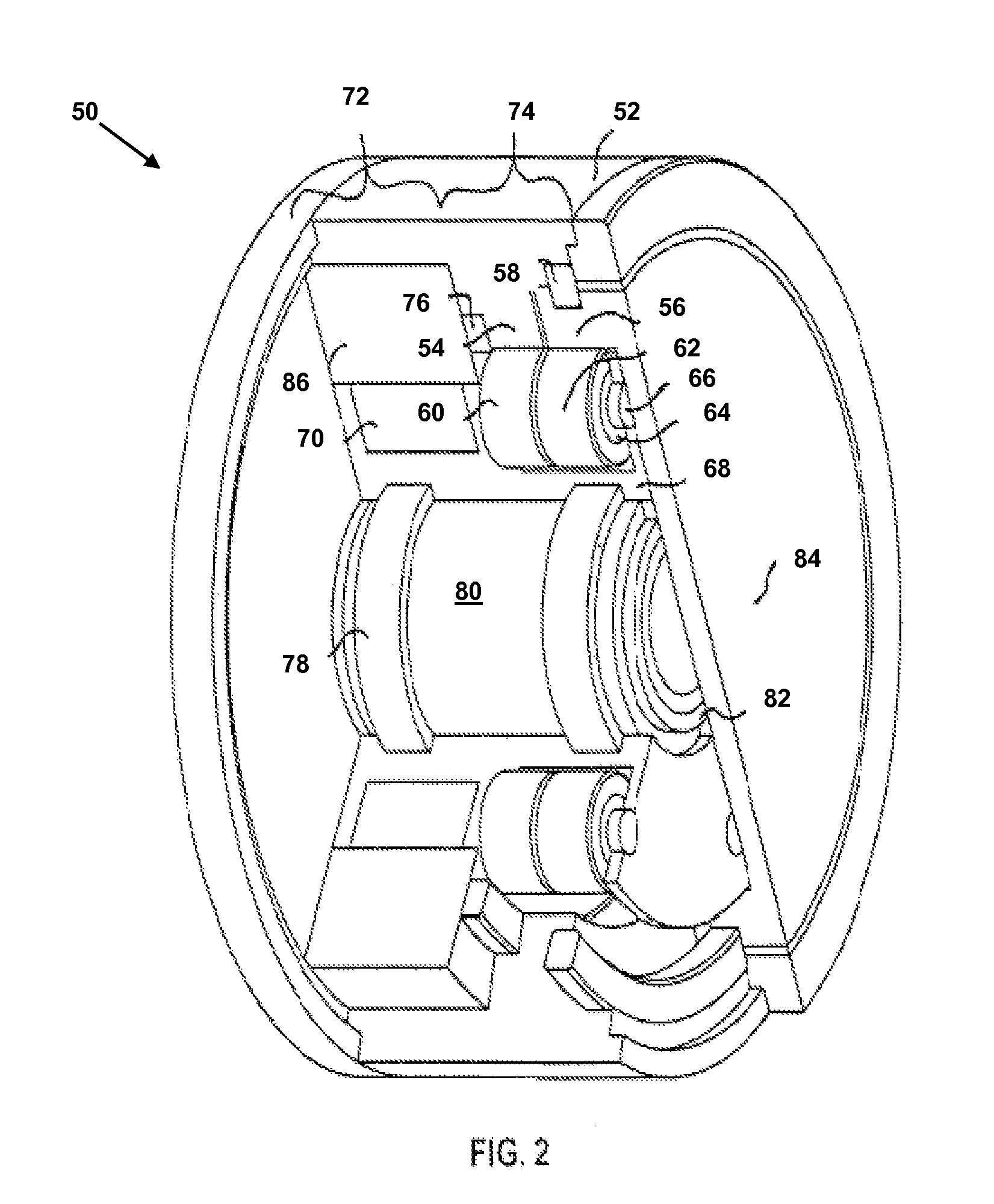
[0054]FIG. 2 depicts rotary actuator 50 in an isometric cutaway view in accordance with the present disclosure. Rotary actuator 50 is typically longer than rotary actuator 10, and there is more concern for the stiffness of the planet cage 68. Accordingly, additional support is provided by bearing 76, embedded in the stiff attachment shell 52 of actuator 50. In order to simplify the design of rotary actuator 50, the planets 60 and 62 are supported by bearings 64 which ride on shafts 66, which are press fit into the planet cage 68 to further increase the stiffness of planet cage 68.

[0055]The output attachment plate 84 and central stationary shaft 230 are mutually supported by bearing 82. Generally, because of higher velocities in the D.C. motor, the structure of the planet cage 68 will be lightened to reduce inertia and the bearings 58, 64, and 76 will be chosen for this higher velocity regime.

[0056]As will be appreciated by those of skill in the art, additional planets tend to increa...

fourth embodiment

[0079]FIG. 4, depicts a cutaway isometric view of a rotary actuator 130 in accordance with the present disclosure. The rotary actuator 130 incorporates a central stationary shaft 156 holding support bearings 155 that support the rotating motor armature 148 that drives the eccentric 157. Support bearings 144 on the eccentric 147 drive the wobble cylinder, which contains the planetary gears 140 and 142 that mesh with the bull gear 134 and sun gear 136 separated by the principal cross-roller bearing or similar large diameter bearing 138.

[0080]Rotary actuator 130 employs a pancake configuration that incorporates an SRM prime mover 150 to produce a high torque / low speed rotary actuator 130.

[0081]Bearing 158 in the output attachment plate 160 supports the end of the stationary shaft 156. Seal 164 separates the output attachment plate 160 from the shell 132 and protects the cross-roller bearing 138 from the elements.

[0082]FIG. 5 depicts a cutaway isometric view of a rotary actuator 170 in ...


PUM


Abstract

A parallel eccentric electro-mechanical actuator provides motive power and includes an electric prime mover that drives the reducer's pinion gear. This pinion drives minimum three star gears with stationary shaft bearings. Each shaft contains an eccentric which are completely in parallel with each other. These eccentrics can be thought of as parallel / in-phase driven crankshafts. Each eccentric drives the parallel eccentric (PE) gear through a bearing. The PE gear exhibits a circular motion (without rotation) which in itself is unbalanced. The crankshafts have another eccentric which create an opposite inertia force to balance that of the PE gear. The PE gear contains an external toothed gear on its periphery. It meshes with the internal teeth of the output ring gear. The relative motion between the PE gear and the ring gear is that the PE gear rolls inside the ring gear. This relative motion is called hypo-cycloidal motion.

Description

RELATED APPLICATIONS[0001]This is a continuation-in-part of U.S. patent application Ser. No. 11 / 288,042 filed Nov. 28, 2005, which is a continuation-in-part of U.S. patent application Ser. No. 10 / 714,183, filed Nov. 14, 2003, now U.S. Pat. No. 7,081,062, which claims priority of U.S. Provisional Patent Application Ser. No. 60 / 429,276, filed Nov. 25, 2002. This continuation-in-part application also claims priority to U.S. Provisional Patent Application No. 60 / 890,246 filed Feb. 16, 2007.FIELD[0002]The present disclosure relates in general to rotary power devices, and specifically to rotary actuators for use in automated machinery.DESCRIPTION OF THE RELATED ART[0003]Currently the design of mechanical systems using actuators is a complex task with many options to choose from, each option with inherent flaws and shortcomings. The narrow reduction range of these options keeps the system from being versatile, which may be expensive and wasteful. Customizing the system to such small ranges...

Claims


Application Information

Patent Timeline
Patent Type & Authority Patents(United States)
IPC IPC(8): F16H23/00
CPCF16H1/28F16H1/32H02K7/116Y10T74/19888F16H2001/2881F16H1/46
Inventor TESAR, DELBERT
Owner TESAR DELBERT
Why Eureka
Try Eureka