Method and device for manufacturing a three-dimensional object

a three-dimensional object and manufacturing method technology, applied in the direction of manufacturing tools, electric/magnetic/electromagnetic heating, coatings, etc., can solve the problems of affecting the quality of the surface, the mechanical properties of the whole part are spoiled, and the methods have similar disadvantages, so as to improve the mechanical properties of the manufactured object

Active Publication Date: 2011-10-11
EOS ELECTRO OPTICAL SYST
View PDF19 Cites 107 Cited by
  • Summary
  • Abstract
  • Description
  • Claims
  • Application Information

AI Technical Summary

Benefits of technology

[0006]It is an object of the present invention to provide a method for manufacturing a three-dimensional object and a device for performing the method, wherein the mechanical properties of the manufactured objects are improved.
[0007]The method according to the invention has the advantage that the formation of stress in the part is homogenized. Moreover, transitions of the partial areas or starting points for the exposure of partial areas are arranged such that they do not form any lines or areas in the object. Thereby, weak spots are avoided and tensions are reduced and / or homogenized.
[0008]The mechanical properties and the exactness of an object that is formed in such a way are improved.

Problems solved by technology

These methods have disadvantages.
An anisotropy that results from a numerous repetition of few exposure directions leads to a spoiling of the mechanical properties of the whole part.
Also the quality of the surface may be affected, e.g. pore formation may occur.
Therefore, these methods have similar disadvantages.

Method used


Image

  • Method and device for manufacturing a three-dimensional object
  • Method and device for manufacturing a three-dimensional object
  • Method and device for manufacturing a three-dimensional object

Examples


Embodiment Construction

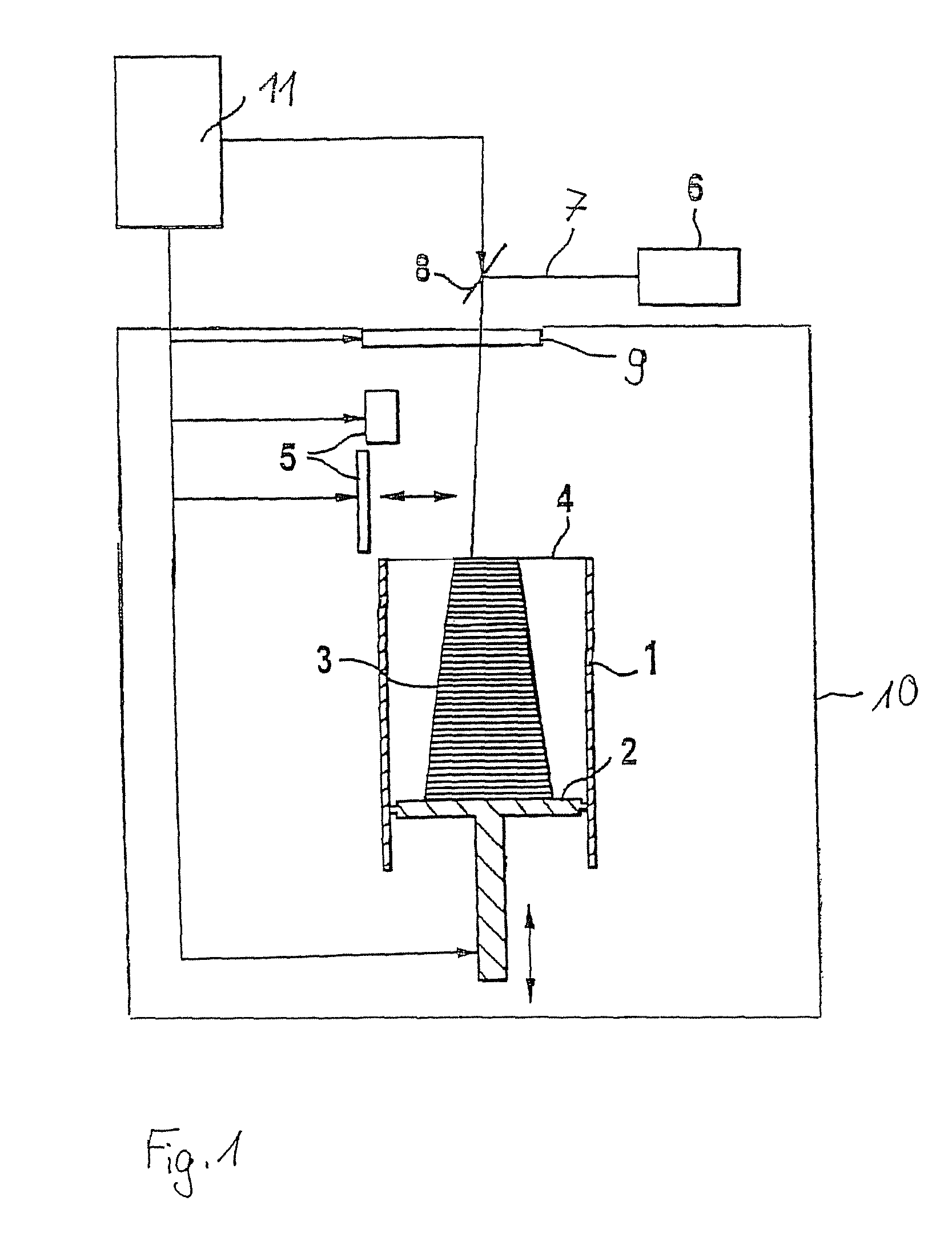
[0016]FIG. 1 shows a laser sintering device as an embodiment of a device for a layer-wise manufacturing of a three-dimensional object. The laser sintering device comprises the container 1, which is open to the top, having therein a support 2, which can be moved in a vertical direction and supports the object 3 to be manufactured. The support 2 is positioned in a vertical direction such that at each time a layer of the object to be solidified lies in a working plane 4. Further, an application device 5 is provided for applying the building material in powder form that is to be solidified by means of electromagnetic radiation. Furthermore, the device comprises a laser 6. The laser beam 7 that is generated by the laser 6 is directed to a window 9 by a deflection device 8. The window 9 lets the laser beam pass through into the process chamber 10 and focuses it on a pre-determined point in the working plane. Usually a focusing optics (not shown) is provided. The deflection device 8 consis...


PUM

PropertyMeasurementUnit
angleaaaaaaaaaa
angleaaaaaaaaaa
angleaaaaaaaaaa

Abstract

A method for manufacturing a three-dimensional object by successively solidifying layers of a building material at positions in the respective layer corresponding to the cross-section of the object is provided, wherein at least a partial region of a layer is solidified such that a pattern is generated, which pattern contains a plurality of substantially parallel solidification lines (V, S), and at least a partial region of a subsequent layer is exposed such that a pattern is generated, which pattern contains a plurality of substantially parallel solidification lines (V, S) that are rotated with respect to the solidification lines of the pattern of the previous layer by an angle (α) that differs from 180°, 90° and 45°.

Description

BACKGROUND OF THE INVENTION[0001]The invention is related to a method and a device for manufacturing a three-dimensional object by a successive linear solidification of layers of a building material at positions in the respective layer corresponding to the cross-section of the object.[0002]In laser sintering as well as in stereolithography and other related layer-wise manufacturing methods there are known various exposure patterns for filling regions, i.e. regions that are located in the respective layer inside of the contour defining the outline of the object.[0003]In particular in order to minimize shrinkage effects and residual stress there have been developed exposure patterns that divide the area to be exposed into partial areas and expose these in differing sequences if necessary. Such exposure patterns are for example described in EP 0 429 196 B1, DE 42 33 812 C1 for stereolithography and in DE 100 42 134 C2 for laser sintering. Typically, the direction of the exposure vector...

Claims


Application Information

Patent Timeline
Patent Type & Authority Patents(United States)
IPC IPC(8): B29C35/08B29C41/02
CPCB22F3/1055B29C67/0066B29C67/0088B22F2003/1057B29C64/135B33Y30/00B33Y10/00B29C64/393Y02P10/25B22F10/18B22F12/43B22F10/366B22F10/28B22F12/60B22F12/30
Inventor DIMTER, MARCMAYER, RALPHHUMMELER, LUDGERSALZBERGER, RAINERKOTILA, JUHASYVANEN, TATU
Owner EOS ELECTRO OPTICAL SYST
Why Eureka
Try Eureka