Pick and place apparatus

a technology of picking and placing apparatus, which is applied in the direction of furniture parts, semiconductor/solid-state device testing/measurement, instruments, etc., can solve the problems of low endurance and reliability of the apparatus, structural limits in the size of the apparatus, operation characteristics and production efficiency, etc., to prevent deterioration in the performance of the apparatus, improve the endurance and reliability, and increase the size of the linear motion guide mechanism

Active Publication Date: 2011-10-18
TECHWING CO LTD
View PDF16 Cites 11 Cited by
  • Summary
  • Abstract
  • Description
  • Claims
  • Application Information

AI Technical Summary

Benefits of technology

[0018]It is, therefore, a first object of the present invention to provide a pick and place apparatus capable of improving its endurance and reliability by increasing the size of a linear motion guide mechanism, while preventing deterioration in performance of the apparatus by reducing the entire size and weight of the apparatus.
[0019]It is a second object of the present invention to provide a pick and place apparatus allowing a simple and easy tolerance management, thus improving productivity and reducing manufacturing costs.
[0020]It is a third object of the present invention to provide a pick and place apparatus capable of accomplishing the first and the second object more effectively in a configuration where device holding elements are arranged in a front row and a rear row symmetrically.

Problems solved by technology

However, the size increase of the guide rail and the coupling blocks would also result in the problem of weight increase of the apparatus.
However, the conventional pick and place apparatus, which has the configuration where each of the device holding elements is engaged with both of the linear motion guide mechanisms, has structural limits in its size, operational characteristics and production efficiency.
Thus, a small-size LM guide with a LM block of a small width is usually employed in the field, bearing the low endurance and reliability of the apparatus.
Thus, the cycle of maintenance of the pick and place apparatus is very short.
Specifically, when using a small-size LM guide with a LM block of a small width, though it is intended to complement the bolt coupling force between the device holding element and the LM block is intended, such a coupling method is incomplete in view of the characteristic of the pick and place apparatus that its operation is repeated for a long period of time.
Thus, frequent maintenance works are needed.
Further, if the LM guide 13 is designed to have a size smaller than the required size to reduce the size of the pick and place apparatus, the bolt tightening torque having a direct influence on the operational characteristic of the LM guide 13 should be controlled very precisely in the manufacturing process of the pick and place apparatus, which is very troublesome.
Thus, when using the LM guide 13 whose size is smaller than the required size, a precise control of the bolt tightening torque is needed, which would result in deterioration in production efficiency and increase of production of inferior goods.
Accordingly, the unit cost of the LM guides 13 and 14 increases, resulting in increase of manufacturing costs of the pick and place apparatus.
Actually, however, it is impossible to set the Z-axial tolerances and parallelisms of three different related parts in a general manufacture or assembly technique.
Thus, the unit cost of a frame of the pick and place apparatus having the LM guides 13, 14 and the screw guide shaft fixed thereat would be increased, which would result in a great increase of manufacturing costs of the pick and place apparatus.

Method used


Image

  • Pick and place apparatus
  • Pick and place apparatus
  • Pick and place apparatus

Examples


Embodiment Construction

[0032]Hereinafter, embodiments of the present invention will be described in detail with reference to the accompanying drawings.

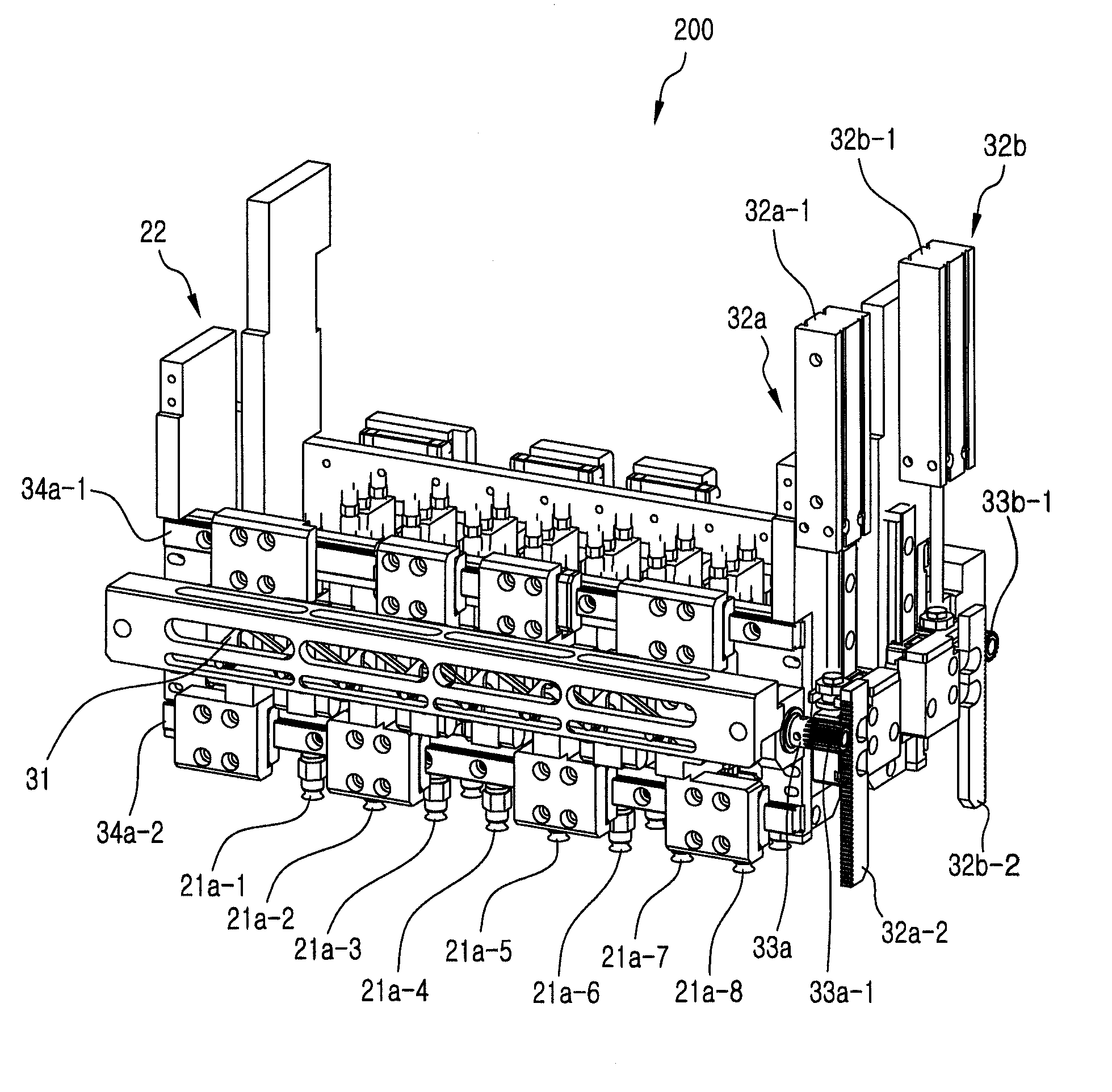
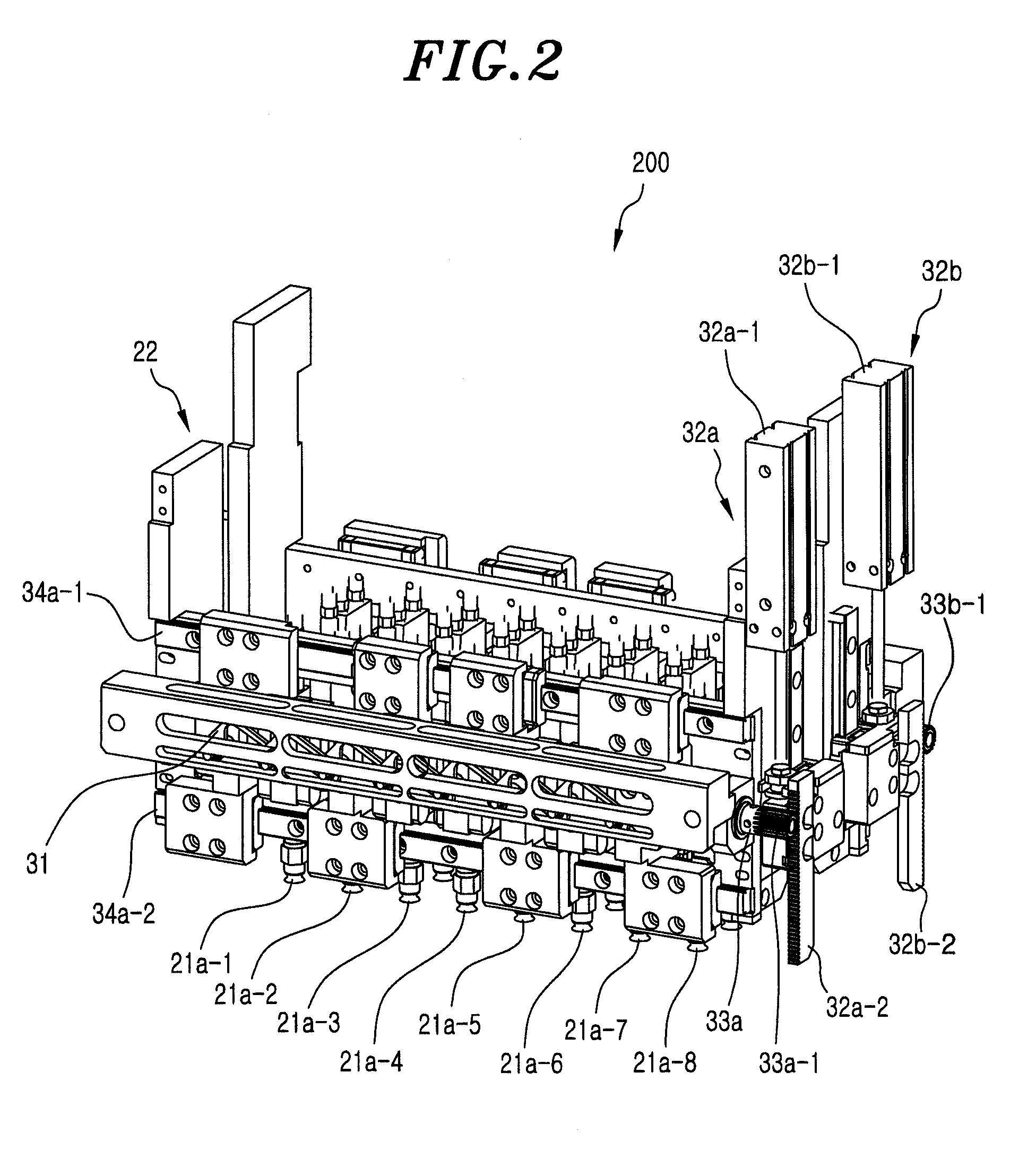
[0033]FIG. 2 sets a front perspective view of a pick and place apparatus 200 in accordance with a embodiment of the present invention; FIG. 3 shows a front view of the pick and place apparatus 200 in FIG. 2; and FIG. 4 presents a perspective view of major components of the pick and place apparatus 200 in FIG. 2.

[0034]The pick and place apparatus 200 shown in FIG. 2 is invented by combining the present invention with the technical conception of Korean Patent Application No. 2005-17464 that was commonly assigned to the applicant of the present invention prior to the filing date of the present application, wherein the pick and place apparatus 200 is described for the case of employing a screw guide shaft for allowing a plurality of device holding elements to move in a horizontal direction.

[0035]Referring to FIGS. 2 to 4, the pick and place apparatus 200 includ...


PUM


Abstract

A pick and place apparatus includes a plurality of device holing elements in a predetermined arrangement; a power supply mechanism for supplying a power for controlling a horizontal pitch between the plurality of device holding elements; a power transmission mechanism for delivering the power from the power supply mechanism to the plurality of device holding elements as a translational force in a horizontal direction; a first linear motion guide mechanism for guiding horizontal movements of some of the plurality of device holding elements; and a second linear motion guide mechanism disposed below the first linear motion guide mechanism, for guiding horizontal movements of the other device holding elements. The plurality of device holding elements are slidably coupled to the first and the second linear motion guide mechanism alternately.

Description

[0001]This application is a Continuation Application of PCT International Application No. PCT / KR2006 / 004934 filed on Nov. 22, 2006, which designated the United States.FIELD OF THE INVENTION[0002]The present invention relates to a pick and place apparatus employed in a test handler for use in testing semiconductor devices; and, more particularly, to a coupling mechanism between the device holding elements in the pick and place apparatus and a linear motion guide for guiding movements of the device holding elements in a left-and-right direction (in general, defined as an X-axis direction and hereinafter, referred to as a “horizontal direction”).BACKGROUND OF THE INVENTION[0003]A test handler is an apparatus for testing semiconductor devices in a certain test environment to inspect the qualities of the semiconductor devices after they are fabricated. Techniques related to the test handler are disclosed in many published documents including Korean Patent Publication No. 2003-0029266 (en...

Claims


Application Information

Patent Timeline
Patent Type & Authority Patents(United States)
IPC IPC(8): B25J15/06B65G47/91
CPCG01R31/2893H05K13/0482H01L21/50H01L22/00H01L21/68
Inventor SHIM, JAE GYUNNA, YUN SUNGJEON, IN GUKU, TAE HUNGYO, DONG HYUN
Owner TECHWING CO LTD
Why Eureka
Try Eureka