
Solar collector with reflector having compound curvature

a solar collector and reflector technology, applied in the field of solar technologies, can solve the problems non-continuous flux lines on solar receivers, etc., and achieve the effect of reducing the efficiency of photovoltaic cells and more uniform exposure to reflected sunligh

Active Publication Date: 2011-10-18
SKYLINE SOLAR INC +1
View PDF21 Cites 33 Cited by
  • Summary
  • Abstract
  • Description
  • Claims
  • Application Information

AI Technical Summary

Benefits of technology

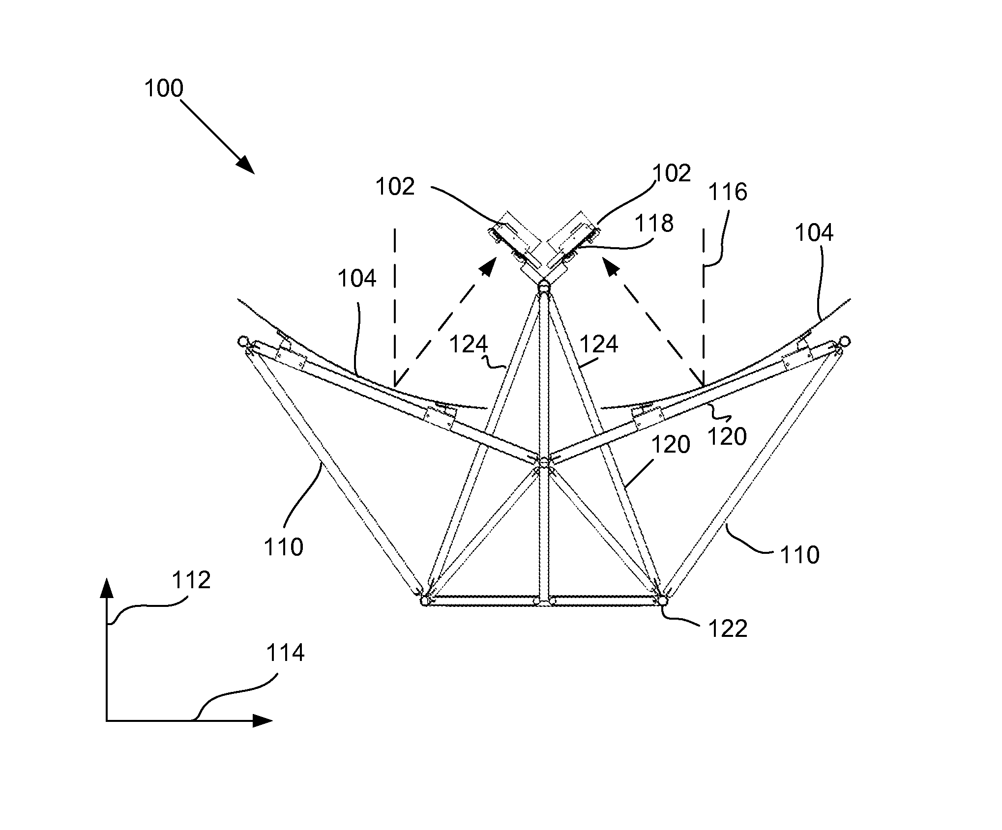
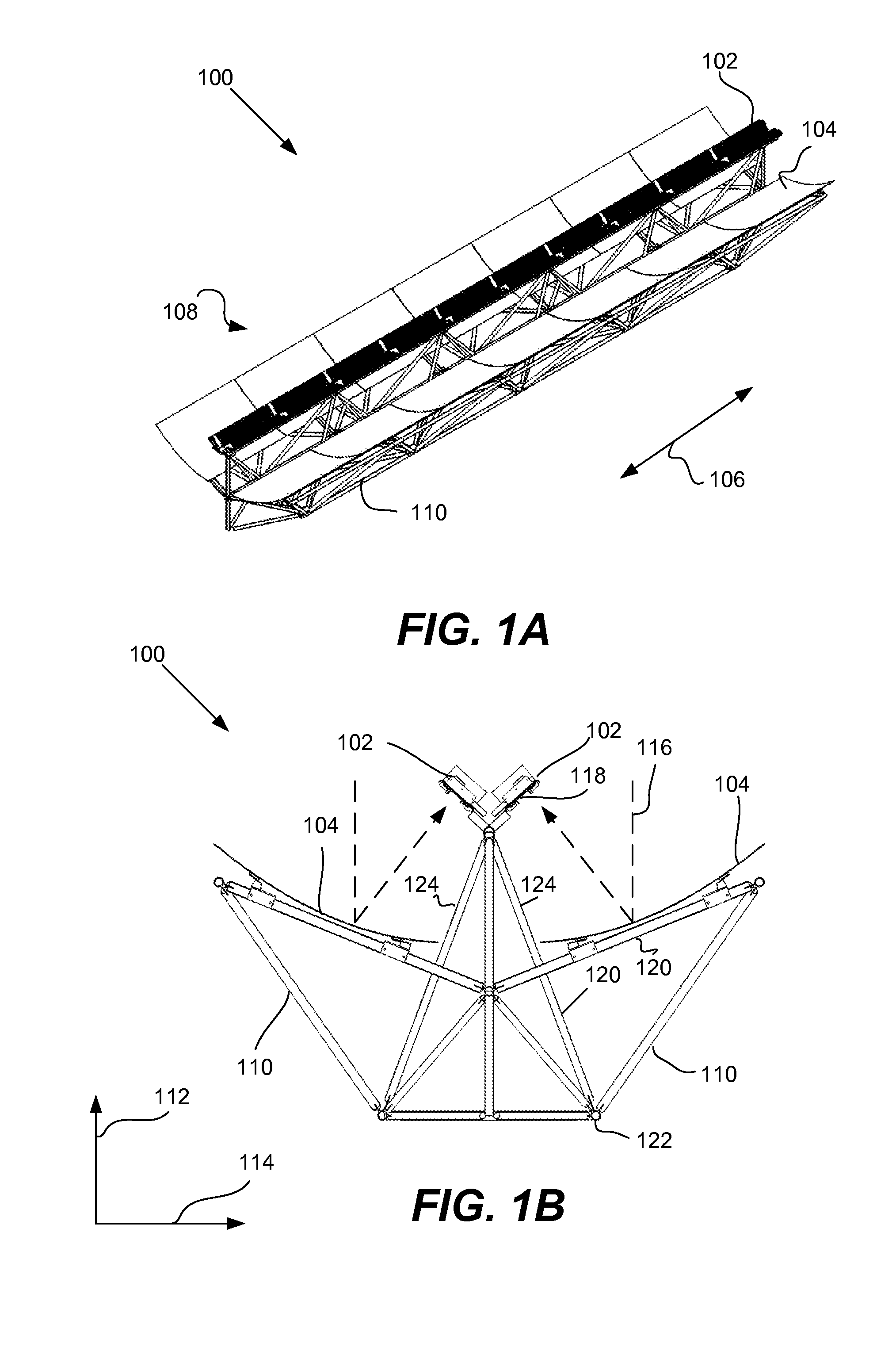
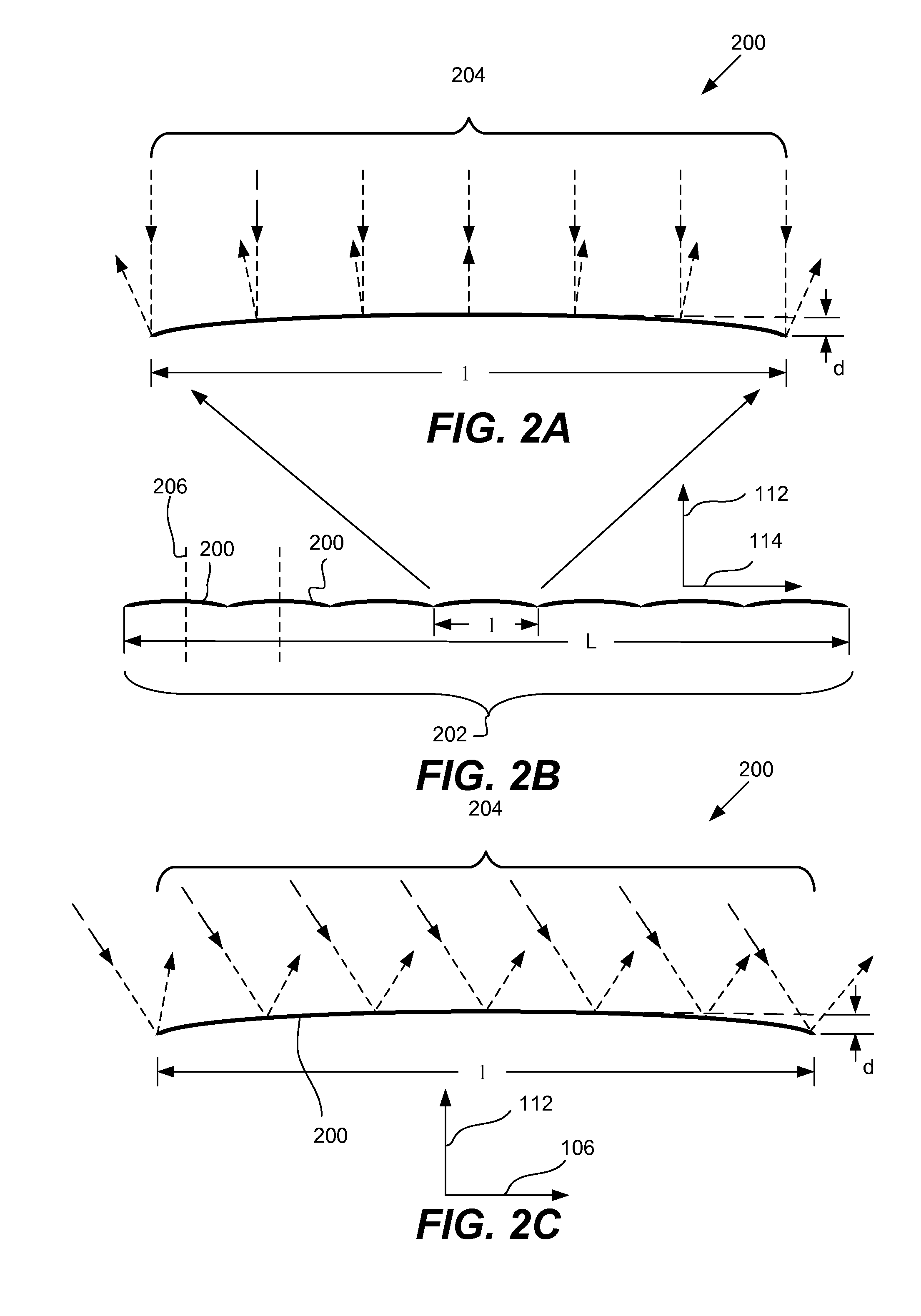
[0005]One aspect of the present invention relates to a photovoltaic solar energy collector suitable for use in a solar energy collection system that includes a stand and a tracking system. The solar collector includes one or more reflector panels, one or more solar receivers, and a support structure. In this aspect of the present invention, the reflective panel has a compound curvature. That is, the reflective panel has a concave shape in one direction that is suitable for directing incident light to form a flux line on the solar receivers. The reflective panel also has a slightly convex shape in another direction. This compound curvature offers various advantages. For example, gaps may form in or between the reflector panels that can cause the flux line on the solar receivers to be non-continuous. This can reduce the efficiency of the photovoltaic cells. The convex curvature, by spreading out the light reflected by each reflector panel, can help wash out such gaps and maintain the continuity of the flux line making the flux line more longitudinally uniform As a result, the photovoltaic cells on the collector receive more uniform exposure to reflected sunlight.
[0007]In another aspect of the invention, the support structure for the solar collector is a space frame. That is, the support structure is formed from interlocking linear struts that are connected at nodes. There are large apertures and spaces between the struts that allow the free flow of air through the space frame, thereby reducing the wind load on the solar collector. The space frame support structure includes receiver support struts and reflector support struts. In various implementations, the receiver and reflector support struts are integrated into a unitary space frame support structure. That is, struts and nodes are arranged such that the loads from the reflectors and receivers are not carried entirely by the struts that are immediately attached to them. In various preferred embodiments, these loads are instead dispersed more widely through the space frame support structure.

Problems solved by technology

For example, gaps may form in or between the reflector panels that can cause the flux line on the solar receivers to be non-continuous.
This can reduce the efficiency of the photovoltaic cells.

Method used


Image

  • Solar collector with reflector having compound curvature
  • Solar collector with reflector having compound curvature
  • Solar collector with reflector having compound curvature

Examples


Embodiment Construction

[0025]The present invention relates generally to concentrating photovoltaic systems. The assignee for the present application, Skyline Solar, Inc., has received multiple patents related to such technologies, such as U.S. Pat. No. 7,709,730, entitled “Dual Trough Concentrating Solar Photovoltaic Module,” filed Apr. 10, 2008, which is hereby incorporated by reference in its entirety for all purposes and is hereinafter referred to as the '730 patent.

[0026]The '730 patent describes various solar collector designs that involve a trough-shaped reflector that directs incident sunlight to a string of photovoltaic cells. The described designs work well for many applications. During the course of installing, manufacturing and operating solar energy collection systems, however, the assignee has identified various areas in which the designs could be further improved. For example, ordinary wear and tear can form gaps in the reflector. This can skew the reflection of light by the reflector and ma...


PUM


Abstract

The present invention relates to a solar energy collector suitable for use in a solar energy collection system. The solar energy collection system includes the collector, a stand that supports the collector and a tracking system that causes the collector to track movements of the sun along at least one axis. The collector includes one or more reflector panels, one or more solar receivers, and a support structure that physically supports the reflector panels and solar receivers. Some designs involve a reflector panel that has a compound curvature. That is, the reflector panel has a convex shape along one direction and a concave shape in another direction. In another aspect of the invention, the collector includes a space frame support structure.

Description

CROSS-REFERENCE TO RELATED APPLICATION(S)[0001]The present invention claims priority to U.S. Provisional Application No. 61 / 362,591, entitled “Optimized Solar Collector,” filed Jul. 8, 2010, which is incorporated herein in its entirety for all purposes.FIELD OF THE INVENTION[0002]The present invention relates to solar technologies. More specifically, the present invention relates to various collector, reflector and support structure designs for use in concentrating photovoltaic systems.BACKGROUND OF THE INVENTION[0003]Typically, the most expensive component of a photovoltaic (PV) solar collection system is the photovoltaic cell. To help conserve photovoltaic material, concentrating photovoltaic (CPV) systems use minors or lenses to concentrate solar radiation on a smaller cell area. Since the material used to make the optical concentrator is less expensive than the material used to make the cells, CPV systems are thought to be more cost-effective than conventional PV systems.[0004]O...

Claims


Application Information

Patent Timeline
Patent Type & Authority Patents(United States)
IPC IPC(8): G01C21/02F24S23/70F24S23/71F24S50/20
CPCF24J2/1047F24J2/14H01L31/0547F24J2/541F24J2/5233Y02E10/45Y02E10/47Y02E10/52F24S23/74F24S23/80F24S25/13F24S30/425Y02E10/40
Inventor LANCE, TAMIRFINOT, MARC A.CHAU, MANG V.ACKLER, HAROLD D.WYLIE, CAMERON G.IGNAUT, BRIAN J.
Owner SKYLINE SOLAR INC
Learn More